background image

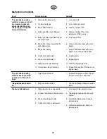
Breaks in work

1.

Turn pressure regulator to the left.

2.

Open release valve  

k

, see page 28.

3.

Switch off unit.

4.

Open trigger of the spray gun in order to release the
pressure from the high-pressure hose and spray
gun.

5.

Secure the spray gun, see Operating manual of the
spray gun.

6.

If the tip is to be cleaned see instructions
page 37.

7.

Leave intake pipe in the coating material or place in
an appropriate cleaning agent. 
The intake pipe, filter and unit should not be allowed
to dry out.

Attention

When using quick-drying or two-component coating
materials, always rinse unit with an appropriate
cleaning agent before they harden.

Placing out of operation and cleaning the
unit

Cleanliness is the best guarantee for a problem-free
operation. Clean the unit after work has been finished.
No left over coating materials should be allowed to dry
and solidify in the unit. The appropriate cleaning agent
for the coating material (only those with a flash point
over 21 

°

C) should be used.

1.

Secure the spray gun, 

see Operating manual of the

spray gun.
Dismantle and clean the tip, see Page 37.

2.

Swivel intake hose and place into an appropriate cle-
aning agent. Release the safety unit on the spray
gun. Open trigger, pump the remaining coating
material from the high-pressure hose and spray gun
into the coating material container. If the coating
material contains solvents earth coating material
container.

Caution! Never pump or spray into a container
with only a small opening (bunghole), see safety
regulations page 24.

3.

Run unit with opened spray gun, re-circulating the
cleaning agent, until pure cleaning agent comes out.

4.

Open release valve  

k

 (see page 28)  in order to

remove the remaining coating material from the
return hose.

5.

Remove intake hose from cleaning agent. Close
release valve 

p

, see page 28. Pump cleaning

agent into a collecting container, thus emptying the
unit of cleaning agent.

6.

Clean all filters. Thoroughly clean the outside of the
spray gun and high-pressure hose.

Attention
The unit should not be left under pressure when
work has been finished. Open release valve


k

,

turn pressure regulator to the left as far as it will
go (minimum pressure).

7.

Shutting down for a longer period of time (holiday
period). Clean unit thoroughly. Then quickly rinse
using engine oil (e.g. SAE 15 – W 40) in order to
protect the unit.

8.

Switch off unit.

9.

High-pressure filter

When working on the high-pressure filter switch
off unit and release pressure.

Open release valve  

k

.

Open high-pressure filter, unscrew filter housing.
Clean all parts using an appropriate cleaning agent.
If compressed air is available blow through filter
insert and support. Reassemble high-pressure filter.
Tighten the filter housing by hand.

10.

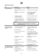
A harsh jet should never be used to spray the
unit. In particular a high-pressure or high-pres-
sure steam cleaner should never be used. There
is a danger that water will penetrate into the unit
and cause a short-circuit.

31

GB

Summary of Contents for EP 3000

Page 1: ...ating manual p 22 Mode d emploi p 44 Airless Hochdruck Spritzgerät Airless high pressure spraying unit Groupe de projection à haute pression EP 3000 EP3000 D R U C K P re ss ur e WAG NE R G15 0256 882 Ausgabe 12 2002 Edition ...

Page 2: ...eachten 1 Fehlerhafte Geräte dürfen nicht benutzt werden 2 Wagner Spritzpistole sichern mit Sicherungshebel am Abzugsbügel 3 Erdung sicherstellen Der Anschluss muss über eine vor schriftsmäßig geerdete Schutzkontakt Steckdose erfolgen 4 zulässigen Betriebsdruck vom Hochdruckschlauch und Spritzpistole überprüfen 5 alle Verbindungsteile auf Dichtheit prüfen Anweisungen zur regelmäßigen Reinigung und...

Page 3: ...auch 8 Behandlung des Hochdruckschlauches 8 Arbeitsunterbrechung 9 Außerbetriebnahme und Reinigung des Gerätes 9 Seite Behebung von Störungen 10 11 Wartung 12 Rückstoßkraft Diagramm für Airless Düsen 13 Düsenauswahl 13 Airless Düsen Tabelle 14 Volumenstrom Tabelle 15 Wartung und Reinigung von Airless Hartmetall Düsen 15 Spritzpistolen Zubehör 15 Ersatzteilliste Hochdruck Spritzgerät WAGNER EP 3000...

Page 4: ...teller der verwendeten Stoffe Lösemittel und Reiniger zu beachten Zum Schutz der Haut sind Schutzkleidung Handschuhe und eventuell Hautschutzcreme erforderlich 7 Die Spritzpistole und der Hochdruckschlauch zwischen Gerät und Spritzpistole müssen dem im Gerät erzeugten Druck entsprechen Eine dauerhafte Kennzeichnung auf dem Hochdruck schlauch muß den zulässigen Betriebsdruck den Herstel ler und das...

Page 5: ...inkstaub und Eisenglimmerfarben Spritzspachtel spritzbare Kleber und bitumenähnliche Beschichtungs stoffe Die Verarbeitung anderer Beschichtungsstoffe ist nur mit Zustimmung der Firma WAGNER zulässig Technische Daten Spannung 230 V 50 Hz 400 V 50 Hz V3 Motorleistung P1 230 V 3 1 kW 400 V 2 9 kW Schutzart IP 54 Absicherung 16 A träge Netzkabel 6 m lang Leergewicht 88 kg max Schalldruckpegel 84 dB A...

Page 6: ...ichern und Abzugsbügel betätigen 4 Entlastungshahn öffnen 2 Hebel umgelegt 5 Filtergehäuse abschrauben 6 Filterpatrone reinigen oder ersetzen 4 EP3000 D R U C K P re ss u re WAG NER G15 1 3 4 5 6 7 9 8 16 10 13 12 2 15 11 14 1 Spritzpistole G 15 2 Elektromotor 3 Getriebeeinheit 4 Materialförderpumpe 5 Ansaugrohr mit Filter 6 Rücklaufrohr 7 Wagen 8 Entlastungsventil 9 Hochdruckfilter 10 Schaltkaste...

Page 7: ...00 V 50 Hz V3 Länge 6 m Querschnitt 5 x 1 5 mm2 und Bezeichnung HO7 RN F5G1 5 Achtung Es ist unbedingt erforderlich auch ein Ver längerungskabel der obengenannten Ausführung zu verwenden Kabellänge bis 100 m je nach zu verarbei tendem Beschichtungsstoff Das Verlängerungskabel muß ganz abgerollt werden Des weiteren ist auf einwandfreie Kupplungsstücke und Steckerverbindungen zu achten Spannungsabfa...

Page 8: ... Entlastungsventil dient der Sicherheit Druckentlastung dem Ansaugen und Entlüften Hebel umgelegt Entlastungsventil geöffnet Durchgang frei über das Rücklaufrohr zum Material behälter Die Pumpe saugt Beschichtungsstoff an Durch das Rücklaufrohr fließt der Beschichtungsstoff wieder zurück Hebel senkrecht Entlastungsventil geschlossen Die Materialförderpumpe fördert Beschichtungsstoff ent sprechend ...

Page 9: ...7 0 1 D R U C K P r e s s u r e 22 25 24 23 Inbetriebnahme 1 Vor Anschluß an das Stromnetz darauf achten daß die Netzspannung übereinstimmt mit der Angabe auf dem Leistungsschild Der Anschluß muß über eine vorschriftsmäßig ge erdete Schutzkontakt Steckdose erfolgen 2 Spezial Hochdruckschlauch Abb 12 Pos 1 mit Gabelschlüssel an den Hochdruckfilter an schrauben Übergangsstutzen in den Hochdruckschla...

Page 10: ...einhalten Die seitliche Abgrenzung des Spritzstrahles soll nicht zu scharf sein Der Spritzrand sollte allmählich auflockern damit beim nächsten Durch gang leicht überlappt werden kann Die Spritzpistole im mer parallel und im Winkel von 90 zur Spritzfläche füh ren so entsteht am wenigsten Farbnebel Achtung Beim Auftreten sehr scharfer Randzonen und Streifen im Spritzstrahl Betriebsdruck erhöhen ode...

Page 11: ...nde pumpen Bei lösemittelhalti gen Beschichtungsstoffen Beschichtungsstoff Ge binde erden Vorsicht Nicht in Beschichtungsstoff Gebinde mit nur kleiner Öffnung Spundloch pumpen oder spritzen siehe Sicherheitsvorschriften Seite 2 3 Gerät mit abgezogener Spritzpistole im Kreislauf be treiben bis sauberes Reinigungsmittel austritt 4 Entlastungsventil öffnen k siehe Seite 6 um die Beschichtungsstoffres...

Page 12: ...auschen 3 Ansaugrohr am Einlaßventil locker 3 Anschluß reinigen und festziehen 4 Einlaßventil verklebt 4 Ansaugrohr abschrauben Ventilkugel mit Schraubendreher oder Stift leicht anstoßen Bei ausbleibenden Erfolg Einlaßventil entfernen und reinigen 5 Auslaßventil verklebt ver 5 Auslaßventil ausbauen schmutzt oder abgenutzte Teile Teile reinigen oder austauschen 6 Einlaßventil beschädigt 6 Teile aus...

Page 13: ... festziehen oder austauschen 8 Auslaßventil abgenutzte Teile 8 Teile austauschen 9 Einlaßventil abgenutzte Teile 9 Teile austauschen 10 Hochdruckfilter verstopft 10 Hochdruckfilter reinigen 11 Gesamtschlauchlänge zu lang 11 Schlauchlänge kürzen Original Schläuche verwenden Gerät saugt Beschichtungs 1 Rücklaufrohr verstopft 1 Gerät druckentlasten stoff an aber kein Rücklaufrohr entfernen und reinig...

Page 14: ...äglich Trennöl einfüllen Nur so viel einfüllen daß kein Trennöl in das Beschichtungsstoff Gebinde tropft 2 Filter am Ansaugrohr abschrauben Mit einem harten Pinsel und entsprechendem Reinigungsmittel säubern 12 D ...

Page 15: ...auswahl Um eine einwandfreie und rationelle Arbeitsweise zu erzielen ist die Auswahl der Düse von großer Wichtigkeit In vielen Fällen kann die richtige Düse nur über einen Spritzversuch ermittelt werden Einige Regeln hierzu Der Spritzstrahl muß gleichmäßig sein Wenn Streifen im Spritzstrahl erscheinen so ist der Spritzdruck zu gering oder die Viskosität des Beschichtungs stoffes zu hoch Abhilfe Dr...

Page 16: ...090 719 1088 719 1006 719 819 80 0 019 0 48 400 0090 819 1088 819 1006 819 Glimmerfarben 221 20 0 021 0 53 145 0090 221 1088 221 1006 221 Zinkstaubfarben 421 40 0 021 0 53 190 0090 421 1088 421 1006 421 Dispersionen 521 50 0 021 0 53 245 0090 521 1088 521 1006 521 621 60 0 021 0 53 290 0090 621 1088 621 1006 621 821 80 0 021 0 53 375 0090 821 1088 821 1006 821 Rostschutzfarben 223 20 0 023 0 58 15...

Page 17: ...längerung mit schwenkbarem Kniegelenk ohne Düse Länge 100 cm Bestell Nr 0096 015 Länge 200 cm Bestell Nr 0096 016 Länge 300 cm Bestell Nr 0096 017 Düsenverlängerung Länge 15 cm Bestell Nr 0999 320 Länge 30 cm Bestell Nr 0999 321 Länge 45 cm Bestell Nr 0999 322 Länge 60 cm Bestell Nr 0999 323 Wartung und Reinigung von Airless Hartmetall Düsen Standarddüsen Ist eine andere Düsenausführung montiert d...

Page 18: ...7 16 9850 643 9850 643 Schlauchschelle 1 17 0258 308 0258 308 Rohr 1 18 0253 244 0253 244 Filter 1 19 9800 115 9800 115 Sechskantschraube 1 20 9800 320 9800 320 Zylinderschraube 2 23 Hochdruckfilter siehe Seite 18 24 0291 541 0291 541 Druckregelknopf 1 25 9953 670 Motorschutzschalter 230 V 50 Hz 16 A 1 0256 348 Motorschutzschalter 400 V 50 Hz V 3 8 A 1 26 0291 438 0291 438 Deckel 1 27 9802 250 980...

Page 19: ...1 5 1 21 9971 453 O Ring 51 x 2 1 22 0010 754 Einschraubstutzen NPSM 3 8 M 16 x 1 5 1 23 9970 103 Dichtring 1 25 0291 350 Zylinderoberteil 1 26 9894 224 Federscheibe 1 27 0291 412 Druckring 1 28 0111 452 Manschette PE 3 29 0291 377 Manschette Leder 2 30 0291 417 Stützring 1 31 9971 451 O Ring 55 x 2 1 32 0291 353 Zylinderunterteil 1 34 0279 462 Federauflage 1 35 0037 776 Druckfeder 1 36 0258 319 K...

Page 20: ...1 15 0256 216 Entlastungsventil 1 16 9871 027 O Ring 1 17 0291 160 Sensor 1 Ersatzteilliste Hochdruckfilter Ersatzteilbild siehe Seite 68 Ersatzteilliste Wagen Ersatzteilbild siehe Seite 69 Werkzeug Bestell Nr 0256 800 Bestell Nr Benennung Anzahl 9994 683 Werkzeugtasche 1 9991 101 Doppelmaulschlüssel 19 x 22 2 0999 318 Sechskantschraubendreher 1 4 1 9991 202 Sechskantschraubendreher 8 mm 1 9992 50...

Page 21: ... x 1 5 0256 320 Doppelstutzen NPSM 3 8 M 16 x 1 5 für Schlauchpeitsche ohne Abb 11 0096 004 Auslegerpistole 30 cm 0096 019 Auslegerpistole 100 cm 0096 005 Auslegerpistole 150 cm 0096 006 Auslegerpistole 270 cm 12 0345 010 Inline Roller IR 100 13 0256 343 Doppelstutzen NPSM 3 8 für Schlauchverlängerung 14 0268 905 Strukturdüsensatz 4 6 8 10 mm 15 0258 202 Spritzkopf zur Verarbeitung von Airless Spa...

Page 22: ... Bestell Nr 0258 712 Pos Best Nr Benennung 1 0258 714 Materialbehälter 2 0342 205 Ansaugschlauch 3 0258 713 Krümmer 17 Spachtel System Bestell Nr 0258 715 Pos Best Nr Benennung 1 0258 718 Materialbehälter 2 0258 717 Ansaugschlauch 3 0258 716 Krümmer D ...

Page 23: ...nkberg 20 04349 Leipzig Plaußig Tel 0 34 22 98 14 108 0 Telefax 0 34 22 98 14 108 40 a b x e f g i n s Dresden J Wagner GmbH Service Stützpunkt Dresden Joachim Walther Neuhausener Straße 5 09548 Deutscheinsiedel Tel 03 73 62 82 63 Telefax 03 73 62 1 72 20 Münster J Wagner GmbH Service Stützpunkt Münster Eulerstraße 11 48155 Münster Tel 02 51 60 89 60 Telefax 02 51 6 04 96 Ratingen J Wagner GmbH Se...

Page 24: ... 2 Secure WAGNER spray gun using the safety catch on the trigger 3 Ensure that the unit is properly earthed The connection must take place through a correctly earthed two pole and earth socket outlet 4 Check allowable operating pressure of high pressure hose and spray gun 5 Check all connections for leaks The instructions regarding regular cleaning and maintenance of the unit must be strictly obse...

Page 25: ...he high pressure hose 30 Breaks in work 31 Placing out of operation and cleaning the unit 31 Page Malfunction checklist 32 33 Maintenance 34 Theoretical recoil force diagram for Airless spray tips 35 Spray tip selection 35 Airless tip table 36 Flow volume table 37 Maintenance and cleaning of Airless hard metal tips 37 Spray gun accessories 37 Spare parts list high pressure spraying unit Wagner EP ...

Page 26: ...r the high pressure hose the manufacturer and date of manufacture must be indicated by a permanent identification marking on the hose Furthermore it must be constructed so that the electrical resistance between the connections to the unit and the spray gun is equal to or less than one megaohm 8 Under certain conditions the flow speed can cause an electrostatic charge on the unit This could cause s...

Page 27: ...ts dispersion paints flame protection and thick film materials zinc dust and ferric oxide paints spray plaster sprayable adhesives and bitumen like coating materials The use of other coating materials is only permissible with the approval from the company WAGNER Technical data Voltage 230 V 50 Hz 400 V 50 Hz V3 Motor output P1 230 V 3 1 kW 400 V 2 9 kW Protective system IP 54 Fuse protection 16 A ...

Page 28: ... Release the safety unit on the spray gun and open trigger 4 Open release tap 2 lever relocated 5 Unscrew the filter housing 6 Clean or replace filter insert 26 EP3000 D R U C K P re ss u re WAG NER G15 1 3 4 5 6 7 9 8 16 10 13 12 2 15 11 14 1 Spray gun G 15 2 Electric motor 3 Gear unit 4 Material feed pump 5 Intake hose with filter 6 Return hose 7 Trolley 8 Release valve 9 High pressure filter 10...

Page 29: ... HO7 RN F3G2 5 EP 3000 400 V 50 Hz V3 Length 6 m diameter 5 x 1 5 mm2 and specification HO7 RN F5G1 5 Attention It is absolutely necessary that you use an extension cable with the above named specifications Cable length up to 100 m depending on the coating material used The extension cable must be rolled out completely Furthermore make sure that the connections are in perfect working order Loss of...

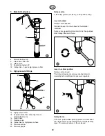
Page 30: ...14 19 16 18 17 15 20 Release valve is for safety pressure release sucking and venting Lever relocated Release valve opened Connection over the return hose to the material container Pump sucks up coating material which is then pumped back through the return hose Lever in vertical position Release valve closed The material feed pump conveys coating material according to the setting on the pressure r...

Page 31: ...1 D R U C K P r e s s u r e 22 25 24 23 Placing into operation 1 Before connecting to the electricity supply ensure that the supply voltage corresponds with the details on the rating plate The connection should be made using a shockproof socket earthed according to regulations 2 Screw the special high pressure hose fig 12 item 1 onto the high pressure filter with open ended spanner Screw connectio...

Page 32: ...rayed The sides of the spray jet should not be too defined The edges should fade away gradually so that the next run can slightly overlap Always move the spray gun parallel and at 90 to the spray surface thus producing the least paint mist Attention If the spray jet has sharp edges and streaks increase operational pressure and thin the coating material Tip blocked See maintenance instructions for ...

Page 33: ...arth coating material container Caution Never pump or spray into a container with only a small opening bunghole see safety regulations page 24 3 Run unit with opened spray gun re circulating the cleaning agent until pure cleaning agent comes out 4 Open release valve k see page 28 in order to remove the remaining coating material from the return hose 5 Remove intake hose from cleaning agent Close r...

Page 34: ...not turned clockwise Remedy 1 Check 2 Replace fuses with 16 A slow blow 3 Use an extension cable with a minimum cross section of 3 x 2 5 mm2 230 V or 5 x 1 5 mm2 400 V 4 The plant must be warmed slightly 5 Replacement by an electrician 6 After about 2 3 minutes switch the motor safety switch back on 1 Fill coating material or immerse intake hose completely in coating material 2 Clean or replace fi...

Page 35: ...o long 1 Return hose blocked 1 Pressure switch defect 1 High pressure hose unsuitable 2 Suction hose loose at intake valve 3 Intake valve leaky or dirty 4 Outlet valve dirty or parts worn Remedy 1 Use correct tip 2 Use smaller or new tip 3 Clean or replace filter 4 Clean or replace filter Have replacement filter ready 5 Use correct filter 6 Clean connection thoroughly and tighten 7 Clean connectio...

Page 36: ...Maintenance 1 Daily Fill lubricant Only enough so that no lubricant drips into coating material container 2 Unscrew intake hose filter Clean with a hard brush and an appropriate cleaning agent 34 GB ...

Page 37: ...ction Selection of the correct tip is essential for correct and efficient spraying In many cases the right tip can be determined only by conducting a spray test Here are a few rules The spray fan must be uniform If streaks appear in the spray fan the spraying pressure is too low or the viscosity of the material is too high Remedy Increase pressure or thin the material Each pump delivers a specific...

Page 38: ...20 0090 719 1088 719 1006 719 819 80 0 019 0 48 400 0090 819 1088 819 1006 819 Mica paints 221 20 0 021 0 53 145 0090 221 1088 221 1006 221 Zinc dust paints 421 40 0 021 0 53 190 0090 421 1088 421 1006 421 Dispersions 521 50 0 021 0 53 245 0090 521 1088 521 1006 521 621 60 0 021 0 53 290 0090 621 1088 621 1006 621 821 80 0 021 0 53 375 0090 821 1088 821 1006 821 Rust protection paints 223 20 0 023...

Page 39: ...stment tip Order no 0097 294 Tip extension with slewable knee joint without tip Length 100 cm Order no 0096 015 Length 200 cm Order no 0096 016 Length 300 cm Order no 0096 017 Tip extension Length 15 cm Order no 0999 320 Length 30 cm Order no 0999 321 Length 45 cm Order no 0999 322 Length 60 cm Order no 0999 323 Maintenance and cleaning of Airless spray tips Standard tips If a different tip type h...

Page 40: ... 16 9850 643 9850 643 Hose clip 1 17 0258 308 0258 308 Tube 1 18 0253 244 0253 244 Filter 1 19 9800 115 9800 115 Hexagon bolt 1 20 9800 320 9800 320 Fillister head screw 2 23 High pressure filter see page 40 24 0291 541 0291 541 Pressure regulator 1 25 9953 670 Motor safety switch 230 V 50 Hz 16 A 1 0256 348 Motor safety switch 400 V 50 Hz V 3 8 A 1 26 0291 438 0291 438 Cover 1 27 9802 250 9802 25...

Page 41: ... x 1 5 1 21 9971 453 O ring 51 x 2 1 22 0010 754 Screwed socket NPSM 3 8 M 16 x 1 5 1 23 9970 103 Sealing ring 1 25 0291 350 Cylinder upper part 1 26 9894 224 Spring washer 1 27 0291 412 Pressure ring 1 28 0111 452 Packing PE 3 29 0291 377 Packing leather 2 30 0291 417 Supporting ring 1 31 9971 451 O ring 55 x 2 1 32 0291 353 Cylinder lower part 1 34 0279 462 Spring rest 1 35 0037 776 Pressure spr...

Page 42: ... 1 15 0256 216 Release valve 1 16 9871 027 O ring 1 17 0291 160 Sensor 1 Spare parts list high pressure filter Spare parts diagram see page 68 Spare parts list trolley Spare parts diagram see page 69 Item Part No Description Qty 1 0291 535 Handle 1 2 9801 202 Screw 2 3 0294 582 Guide 2 4 9841 504 Retaining spring 4 5 0294 580 Stop 2 6 0294 581 Holding bush 2 8 0088 327 Spring washer 2 9 3554 008 S...

Page 43: ...M 3 8 M 16 x 1 5 for hose whip without fig 11 0096 004 Pole gun 30 cm 0096 019 Pole gun 100 cm 0096 005 Pole gun 150 cm 0096 006 Pole gun 270 cm 12 0345 010 Inline Roller IR 100 13 0256 343 Double socket NPSM 3 8 for hose extension 14 0268 905 Texture tip set 4 6 8 10 mm 15 0258 202 Spray tip for use with Airless filler mottled texture with air support 0258 720 Mottled texture set Spray tip textur...

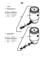
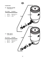
Page 44: ...ystem Part No 0258 712 Item Part No Description 1 0258 714 Material container 2 0342 205 Intake hose 3 0258 713 Elbow 17 Filler system Part No 0258 715 Item Part No Description 1 0258 718 Material container 2 0258 717 Intake hose 3 0258 716 Elbow GB ...

Page 45: ...0528 A B Wagner Spraytech Iberica S A Apartado 132 08750 Molins de Rey Barcelona Spain Phone 93 6800028 Fax 93 6800555 J Wagner France S A R L B P 75 91122 Palaiseau Cedex France Phone 01 60114050 Fax 01 69817257 Wagner Spraytech UK Ltd Unit 3 Haslemere Way Tramway Industrial Estate Banbury Oxon OX 16 8TY Great Britain Phone 0 12 95 265 353 Fax 0 12 95 269 861 J Wagner GmbH HK Room 1801 02 Tai San...

Page 46: ...ecter les points suivants con formément aux instructions de service 1 Ne jamais utiliser un équipement défectueux 2 Verrouiller le pistolet Wagner par le levier de sécurité à la gâchette 3 Assurer la mise à la terre correcte La prise de réseau doit être équipée d un contact de protection terre 4 Vérifier et respecter les pressions admissibles pour le flexible et le pistolet 5 Contrôler l étanchéit...

Page 47: ...ise en service 51 52 Généralités de la technique d application 52 Pistolet 52 Flexible à haute pression 52 Maniement du flexible à haute pression 52 Interruptions de travail 53 Mise hors service et nettoyage 53 Page Dépannage 54 55 Entretien 56 Diagramme de la force de recul des buses 57 Choix des buses 57 Tableau des buses 58 Tableau des débits et des volumes 59 Entretien et nettoyage de buses en...

Page 48: ...entre l équipement et le pistolet doivent correspondre à la pression produite par l équipement Un marquage durable sur le flexible de haute pres sion doit comporter les indications suivantes Pres sion de fonctionnement maxi fabricant et date de fabrication D autre part la résistance entre les rac cords du flexible entre l équipement et le pistolet doit être égale ou inférieure à 1 mégaohm 8 En rai...

Page 49: ...r micacé enduits à projeter colles pulvéri sables et produits de revêtement bitumineux La mise en œuvre d autres produits est soumise à l ac cord préalable des Ets WAGNER Caractéristiques techniques Tension 230 Volt 50 Hz 400 Volt 50 Hz V3 Puissance P1 230 V 3 1 kW du moteur 400 V 2 9 kW Protection IP 54 Fusible 16 A retardé Câble d alimentation 6 m Poids à vide 88 kg Niveau sonore maxi 84 dB A Pr...

Page 50: ...4 Ouvrir la vanne de décharge 2 tourner le levier 5 Dévisser le corps de filtre 6 Nettoyer ou remplacer la cartouche de filtre 48 EP3000 D R U C K P re ss u re WAG NER G15 1 3 4 5 6 7 9 8 16 10 13 12 2 15 11 14 1 Pistolet G 15 2 Moteur électrique 3 Groupe de transmission 4 Pompe de produit 5 Tube d aspiration avec filtre 6 Tube de retour 7 Chariot 8 Vanne de décharge 9 Filtre à haute pression 10 B...

Page 51: ...ur 6 m section 3 x 2 5 mm2 et désignation HO7 RN F3G2 5 EP 3000 400 V 50 Hz V3 Longueur 6 m section 5 x 1 5 mm2 et désignation HO7 RN F5G1 5 Attention Il y a lieu d utiliser obligatoirement un câble de rallonge de la même exécution Longueur du câble jusqu à 100 m en fonction du produit mis en œuvre Le câble de rallonge doit être déroulé complètement D au tre part il faut faire attention au parfait...

Page 52: ... 17 15 20 Vanne de décharge sert à la sécurité décharge de la pression à l aspiration et à la purge d air Levier tourné Vanne de décharge ouverte Le passage par le tube de retour au réservoir de produit est libre La pompe aspire le produit Le produit retourne par le tu be de retour Levier en position verticale La vanne de décharge est fermée La pompe de produit aspire et refoule le produit en fonc...

Page 53: ...étalliques 51 0 1 D R U C K P r e s s u r e 22 25 24 23 Mise en service 1 Avant le branchement au réseau contrôler si la ten sion du réseau correspond à la tension de service in diquée sur la plaque signalétique Le branchement doit être effectué par une prise avec contact de protection relié à la terre 2 Visser le flexible à haute pression spécial fig 12 pos 1 sur le filtre à haute pression en uti...

Page 54: ... bords de projection ne doivent pas être trop nets la distance entre pistolet et support sera donc choisie en conséquence La passe suivante permettra de recouvrir les bords restés assez flous de la passe précédente Si le pistolet est toujours déplacé parallèlement au sup port la formation de brouillard sera minimale Note Si les bords de projection sont trop nets il faut soit aug menter la pression...

Page 55: ...t En cas de produits à base de solvant prévoir la mise à la terre du récipient Attention Ne pas projeter le produit dans un réci pient n ayant qu une seule petite ouverture bonde voir prescriptions de sécurité page 2 3 Laisser tourner le groupe gâchette tirée pendant quelques minutes en circuit fermé 4 Ouvrir la vanne de décharge k voir page 50 pour évacuer les restes du produit du tube de retour ...

Page 56: ...acer le filtre 3 Tube d aspiration à la soupape 3 Nettoyer et serrer le raccord d aspiration desserré 4 Soupape d aspiration collée 4 Dévisser le tube d aspiration Bouger la bille de soupape légèrement avec un tournevis En cas d insuccès démonter et nettoyer la soupape 5 Clapet de refoulement collé 5 Nettoyer ou remplacer le clapet sale ou usé 6 Soupape d aspiration défectueuse 6 Remplacer 7 Pisto...

Page 57: ...le 8 Remplacer les pièces défectueuses ment usés 9 Soupape d aspiration usée 9 Remplacer la soupape 10 Filtre à haute pression bouché 10 Nettoyer le filtre 11 Longueur totale des flexibles 11 Réduire la longueur totale trop importante utiliser des flexibles originaux Le groupe aspire le produit 1 Tube de retour bouché 1 Décharger la pression démonter et qui ne sort toutefois pas nettoyer le tube d...

Page 58: ...ier Remplir l huile de balayage Eviter le trop plein afin que l huile ne tombe pas dans le récipient du produit 2 Dévisser le filtre du tube d aspiration Le nettoyer à l aide d un pinceau dur et du solvant approprié 56 F ...

Page 59: ...es buses Afin d obtenir des bons résultats et pour travailler rationnellement il est très important de choisir les buses appropriées Dans beaucoup de cas ce choix ne peut être fait qu après des essais Voici quelques règles générales à ce sujet Le jet projection doit être uniforme Si l on constate des bandes la pression de projection est trop basse ou le produit est trop visqueux Remède Augmenter l...

Page 60: ...1088 719 1006 719 819 80 0 019 0 48 400 0090 819 1088 819 1006 819 Peintures au mica 221 20 0 021 0 53 145 0090 221 1088 221 1006 221 peintures à base de zinc 421 40 0 021 0 53 190 0090 421 1088 421 1006 421 vinyles 521 50 0 021 0 53 245 0090 521 1088 521 1006 521 621 60 0 021 0 53 290 0090 621 1088 621 1006 621 821 80 0 021 0 53 375 0090 821 1088 821 1006 821 Peintures anti rouille 223 20 0 023 0...

Page 61: ...s Tenir compte des points suivants afin de conserver la propreté et la disponibilité de la buse 1 Ouvrir la vanne de décharge k 2 Arrêter le groupe 3 Démonter la buse du pistolet 4 Mettre la buse dans le diluant approprié jusqu à dilution complète des restes de produit 5 Souffler la buse si l air comprimé est à disposition 6 Avec un objet pointu en bois cure dents enlever les restes éventuels 7 Co...

Page 62: ...43 Collier de serrage 1 17 0258 308 0258 308 Tube d aspiration 1 18 0253 244 0253 244 Filtre 1 19 9800 115 9800 115 Vis hexagonale 1 20 9800 320 9800 320 Vis cylindrique 2 23 Filtre à haute pression voir page 62 24 0291 541 0291 541 Bouton de réglage de la pression 1 25 9953 670 Interrupteur protecteur 230 V 50 Hz 16 A 1 0256 348 Interrupteur protecteur 400 V 50 Hz V 3 8 A 1 26 0291 438 0291 438 C...

Page 63: ...que 51 x 2 1 22 0010 754 Raccord NPSM 3 8 M 16 x 1 5 1 23 9970 103 Joint d étanchéité 1 25 0291 350 Partie supérieur du cylindre 1 26 9894 224 Rondelle ressort 1 27 0291 412 Bague de pression 1 28 0111 452 Garniture PE 3 29 0291 377 Garniture cuir 2 30 0291 417 Bague d appui 1 31 9971 451 Joint torique 55 x 2 1 32 0291 353 Partie inférieure du cylindre 1 34 0279 462 Appui de ressort 1 35 0037 776 ...

Page 64: ... 14 0256 387 Joint d étanchéité 1 15 0256 216 Vanne de décharge 1 16 9871 027 Joint torique 1 17 0291 160 Capteur 1 Liste des pièces de rechange du filtre à haute pression Eclaté voir page 68 Liste des pièces du chariot Eclaté voir page 69 Pos Réf No Désignation Quantité 1 0291 535 Timon 1 2 9801 202 Vis 2 3 0294 582 Guidage 2 4 9841 504 Ressort 4 5 0294 580 Butée 2 6 0294 581 Douille 2 8 0088 327...

Page 65: ...m 0096 019 Pistolet de rallonge 100 cm 0096 005 Pistolet de rallonge 150 cm 0096 006 Pistolet de rallonge 270 cm 12 0345 010 Rouleau distributeur IR 100 13 0256 343 Raccord double NPSM 3 8 pour rallonge de flexible 14 0268 905 Jeu de buse à structure 4 6 8 10 mm 15 0258 202 Tête de projection pour la mise en œuvre d enduits à projeter structure mouchetée avec assistance d air 0258 720 Kit de proje...

Page 66: ... Réf No 0258 712 Pos Réf No Désignation 1 0258 714 Réservoir de produit 2 0342 205 Tuyau d aspiration 3 0258 713 Coude 17 Système pour enduits Réf No 0258 715 Pos Réf No Désignation 1 0258 718 Réservoir de produit 2 0258 717 Tuyau d aspiration 3 0258 716 Coude F ...

Page 67: ...ax 071 7 57 22 22 CH Wagner Spraytech Corp P O Box 9362 Minneapolis 55440 USA Tél 612 553 7000 Fax 612 553 7288 USA Wagner Spraytech Japan Ltd 2 35 Shinden Nishimachi Osaka Japon Tél 720 743561 Fax 720 743426 Japon USINES ET POINTS DE VENTE LE SERVICE CLIENTELE F B RELATION CLIENTELE tél 16 1 60 11 28 28 SERVICE COMMANDES tél 16 1 60 11 40 50 WAGNER FRANCE B P 75 5 Av du 1 Mai 91122 PALAISEAU Céde...

Page 68: ...rät WAGNER EP 3000 Spare parts diagram high pressure spraying unit WAGNER EP 3000 Eclaté du groupe WAGNER EP 3000 D GB F 0 1 D R U C K P re ss u re EP300 0 27 1 2 3 4 5 6 30 9 4 8 10 11 12 13 9 15 16 19 20 4 23 25 25 24 26 28 29 31 18 17 ...

Page 69: ... 7 8 9 12 14 15 14 15 14 16 17 18 20 21 25 23 22 26 27 28 29 28 29 28 30 31 32 34 35 36 37 38 39 67 Ersatzteilbild Materialförderpumpe Spare parts diagram material feed pump Eclaté de la pompe de produit D GB F 12 97 ...

Page 70: ...68 Ersatzteilbild Hochdruckfilter Spare parts diagram high pressure filter Eclaté du filtre à haute pression D GB F 17 1 4 5 6 7 10 9 10 10 13 11 14 16 12 15 2 3 9 ...

Page 71: ...69 Ersatzteilbild Wagen Spare parts diagram trolley Eclaté du chariot D GB F 4 6 5 4 3 2 8 9 8 9 2 3 4 5 6 4 14 14 14 14 15 13 15 13 11 10 12 1 04 97 ...

Page 72: ...erfirma oder uns schriftlich mitzuteilen Wir behalten uns vor die Garantie durch ein Vertragsunternehmen erfüllen zu lassen Die Leistung dieser Garantie ist abhängig vom Nachweis durch Rechnung oder Lieferschein Ergibt die Prüfung dass kein Garantiefall vorliegt so geht die Reparatur zu Lasten des Käufers Klargestellt wird dass diese Garantieerklärung keine Einschränkung der gesetzlichen bzw der d...

Page 73: ...pparent defect should be notified to us or the dealer in writing within 14 days from date of sale of the unit The right to commission warranty services to a third party is reserved Warranty claims are subject to proof of purchase by submitting an invoice or delivery note If an inspection finds damage not covered by the present warranty the repair will be carried out at the expense of the purchaser...

Page 74: ... par l acheteur ou par une tierce personne usure normale erreurs de manipulation ou de maintenance utilisation de produits de revêtement et de matières de remplacement impropres influences chimiques électrochimiques ou électriques ceci bien entendu pour autant que l erreur ne nous est pas imputable Certains produits abrasifs comme par exemple le minium de plomb les peintures vinyliques glacis prod...

Reviews: