background image

16

Basic 8000

.

A

B

B
C

D

B1

B1

P_00478

1

2

Y

X

6

4/1

3

4

5

7

8

P_00479

OPERATING MANUAL

VERSION 12/2010

ORDER NUMBER DOC 3305595

5.3 

ASSEMBLY PROCEDURE

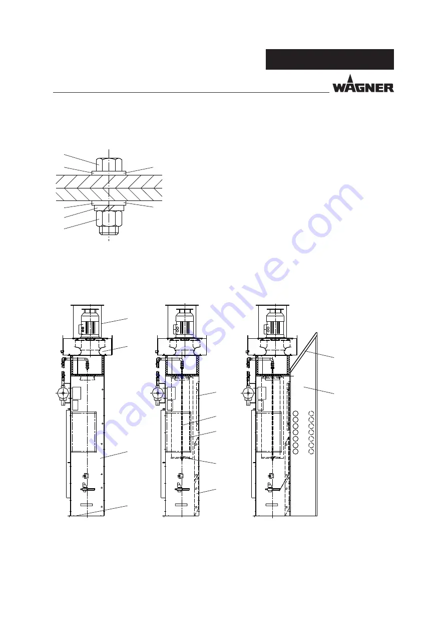
Hint:

On all connections on the booth, the M8 hexagonal screws must 
have washers B below the screw head A and washers B plus 
spring disks C below the hexagon nut D!

To assure a secure grounding between the elements of each
module, the washer B located in at least two positions of every 
module must be replaced by a contact disk B1!

Summary of Contents for Basic 8000

Page 1: ...Spray wall Basic 8000 Version 12 2010 Translation of the original Operating manual ...

Page 2: ......

Page 3: ... Using in accordance with the instructions 8 2 5 Safety features 9 3 WARRANTY AND CONFORMITY DECLARATIONS 10 3 1 Important notes on product liability 10 3 2 Warranty claim 10 3 3 CE conformity 11 4 GENERELL DESCRIPTION 12 4 1 Delivery scope 12 4 2 Technical data 12 4 4 Design and functional description 13 5 ASSEMBLING 14 5 1 Requirements for the installation site 14 5 2 Setting up the system 15 5 ...

Page 4: ...MBER DOC 3305595 Contents 9 SPARE PARTS 27 9 1 How to order spare parts 27 9 2 Spare parts list Basic 8000 spray wall 28 9 3 Spare parts list pressure tank 30 9 4 Spare parts list air diffuser 31 9 5 Connection set of the manual system 32 10 ACCESSORIES 33 ...

Page 5: ...GER This line warns of the hazard Possible consequences of failing to observe the warning instructions The signal word points out the hazard level The measures for preventing the hazard and its consequences SIHI_0103_GB WARNING This line warns of the hazard Possible consequences of failing to observe the warning instructions The signal word points out the hazard level The measures for preventing t...

Page 6: ...d on active parts Secure the control unit against being switched back on without authorisation Inform staff about planned work Observe electrical safety regulations ª Ensure that the floor of the working area is anti static measurement in accordance with EN 1081 ª Ensure that all persons within the working area wear anti static shoes ª Ensure that gloves that are being worn are made of conductive m...

Page 7: ... the powder spray gun at people Before all work on the unit in the event of work interruptions and functional faults Switch off the energy compressed air supply Secure the powder spray gun against actuation Relieve the pressure from the powder spray gun and unit By functional faults Identify and correct the problem proceed as described in chap Trouble shooting The electrostatic charge may in certa...

Page 8: ...0335 2 may be used for getting rid of dust build ups Take note of the processing regulations laid down by the manufacturer of the powder paint being used when preparing or processing the powder Take note of the manufacturer s advice and the relevant environmental protection regulations when disposing of powder paints Implement the prescribed safety measures in particular the wearing of safety glas...

Page 9: ...ard category Ø 100 mm 3 94 inches The label plates which must be attached are shown below High voltage Forbidden for unauthorized persons Explosive atmosphere Forbidden for persons with a cardiac pacemaker Follow the instructions in the operating manual Smoking fire and open light prohibited Wear electrostatically conductive footwear Grounding label Serves as marker to attach a grounding disk whil...

Page 10: ...ion other than the address of the purchaser This warranty does not cover damage caused by Unsuitable or improper use faulty installation or commissioning by the purchaser or a third party normal wear negligent handling defective maintenance unsuitable coating products substitute materials and the action of chemical electrochemical or electrical agents except when the damage is attributable to us T...

Page 11: ... standards in particular EN 12100 1 2004 04 EN 12100 2 2004 04 DIN EN ISO 14121 2007 12 DIN EN 60079 0 2004 12 DIN EN 60079 14 2009 05 DIN EN 60439 1 2005 01 DIN EN 60204 1 2009 10 DIN EN 50050 2002 DIN EN 50177 2010 04 DIN EN 954 1 1997 03 DIN EN 1127 1 2008 02 DIN EN 13463 1 2009 07 DIN EN 12981 2010 06 DIN EN ISO 13850 2008 09 Marking CE Certificate of Conformity The certificate is enclosed with...

Page 12: ...surface 60 m 646 sft Number of filter cartridges 3 Suction performance of the booth 8000 m h 10462 cy Electrical data Input air pressure 220 400 V Input frequency 50 Hz Nominal rating of drive motor 6 kW Pneumatic data Input air pressure 0 6 0 8 MPa 6 8 bar 97 116 psi Air consumption 10 25 Nm h 353 883 cf Necessary air pressure quality according to ISO 8573 1 class 2 Quality class 3 5 2 Sound pres...

Page 13: ...he Basic 8000 spray wall is suitable for continuous operation The air in the booth is suctioned off with the over spray and guided through the deflector grate 4 to the filters 5 The filter elements cartridges are cleaned automatically alternately each filter element is put out of operation and cleaned while the other elements remain in operation The settings of the cleaning cycle depend on the typ...

Page 14: ...ed on site 5 1 REQUIREMENTS FOR THE INSTALLATION SITE Temperature range 0 40 C 32 104 F Max air humidity 75 Electrical connection 220 380 V 50 Hz System ground band or rod grounding according to VDE 0141 low impedance with NYAF 16 mm Compressed air connection 0 6 0 8 MPa 6 8 bar 97 116 psi Compressed air quality according to ISO 8573 1 Quality class 3 5 2 CAUTION For safe operations the system req...

Page 15: ...ity Risk of injury and damage to equipment Only use appropriate lifting tackle crane fork lift for assembly Secure the parts against tipping during transport Cordon off assembly area to keep out unauthorised persons 5 2 1 THE BASIC 8000 SPRAY WALL AS DELIVERED E Grounding label marks the position to attach a grounding disk Consider references in chapter 5 3 Assembly procedure ...

Page 16: ...LY PROCEDURE Hint On all connections on the booth the M8 hexagonal screws must have washers B below the screw head A and washers B plus spring disks C below the hexagon nut D To assure a secure grounding between the elements of each module the washer B located in at least two positions of every module must be replaced by a contact disk B1 ...

Page 17: ... adequate mechanical strength t is important for system security and to achieve an optimum coating that all system components such as workpieces conveyors control unit color supply control unit and booth or spray wall are perfectly grounded The imperfect grounding of a workpiece will result in Dangerous electric charging of the workpiece Very poor wrap around Uneven coating Backspraying to the spr...

Page 18: ...N 12 2010 ORDER NUMBER DOC 3305595 6 START UP SIHI_05011_ENG WARNING Incorrect start up Risk of injury and damage to equipment Starting up may only be performed by trained and authorized persons We recommend that commissioning is carried out by WAGNER personnel ...

Page 19: ...e differential pressure monitor 6 and set it if required normally the factory settings of 2 0 kPa 0 02 bar 0 29 psi need not be changed 8 Check the cleaning system 7 and set if required normally the factory settings need not be changed 6 1 OPERATION AND DISPLAY ELEMENTS 1 Main switch Switches the system on and off 2 Ventilator ON OFF Attention Switch off the ventilator also via the main switch 3 L...

Page 20: ...als provided by the customer are present CAUTION If the cleaning operation is not activated the nominal exhaust output is not reached 6 3 SWITCHING OFF THE SYSTEM During every interruption of operation all powder conveying parts of the entire coating system should be cleaned of residual powder Procedure 1 Switch off the powder feed and the high voltage for the spray gun and secure them against bei...

Page 21: ...eying parts throughout the complete coating system Procedure 1 Keep the suction system of the booth with the filter cleaning system activated 2 Switch off the powder feed and the high voltage for the spray gun and secure them against being switched on unintentionally 3 Clean the parts of the powder feed system and the interior of the boot 4 Scrape the color powder from the booth walls with a rubbe...

Page 22: ... on the following page You will find an exact description of this controller in a separate settings manual article number 3305994 Normally there is no need to make any settings at the LOGO controller and such work should only be done by qualified personnel SIHI_05016_ENG DANGER Incorrect maintenance repair Danger to life and equipment damage Maintenance and repair work may only be carried out by t...

Page 23: ...ESC to change to another menu or to discard the input 2 OK to select the parameters or to close the input 3 Display Menu display 4 Cursor to increase the value 5 Cursor to change to the other parameters 6 Cursor to change to the other parameters 7 Cursor to decrease the value 7 1 1 BASIC FUNCTIONS ...

Page 24: ... AIR CONTAINER The rear of the spray wall 1 Blow off valve Open to drain the compressed air container 2 Pressure regulator with display 3 Compressed air container for the cleaning system SIHI_05018_ENG WARNING Defective parts Risk of injury and damage to the equipment Remedy damage immediately and replace defective parts ...

Page 25: ...ather be recycled in an environmentally correct manner Wagner or one of our dealers will take back your usedWagner waste electrical or electronic equipment and will dispose of it for you in an environmentally friendly way Please contact one of our service points or one of our representatives or us directly to this purpose The compressed air container is normally maintenance free Check the followin...

Page 26: ...d from the blower The filter cartridges are loose or incorrectly installed The seal of the filter cartridge is defective The filter cartridges are damaged Install the filter cartridges correctly Replace the foam rubber gasket Replace the filter cartridges Excessive noise and or vibrations from the housing The ventilator bearings are defective Dust deposits on the ventilator blades Replace the elec...

Page 27: ...freight or mail sea route or overland route etc Marks in spare parts lists Note to column K in the following spare parts lists U Wearing parts Hint No liability is assumed for wearing parts L Not part of standard equipment available however as additional extra 9 SPARE PARTS 9 1 HOW TO ORDER SPARE PARTS WARNING Incorrect maintenance repair Risk of injury and damage to equipment Repairs and part rep...

Page 28: ...28 Basic 8000 X 6 10 11 1 5 4 7 3 2 8 9 X P_00482 OPERATING MANUAL VERSION 12 2010 ORDER NUMBER DOC 3305595 9 2 SPARE PARTS LIST BASIC 8000 SPRAY WALL ...

Page 29: ...idge with sealing washer 2 3 3143547 Threaded bar long 3 3 3143551 Star knob 4 1 3305671 Motor 5 1 3305672 Clockwise rotating impeller 6 1 3145385 Exhaust air muffler 7 1 3025456 Differential pressure monitor 8 1 3145435 Solenoid valve 2 2 way G1 2 24 VDC 9 2 3305061 Coupling socket 10 1 3144945 Deflector 11 1 3144959 Deflector grid ...

Page 30: ... VAC up to 09 2007 2 3 3306274 Solenoid 24 VDC from 09 2007 3 3 9955654 Valve connector MSSD C 230 VAC up to 09 2007 3 3 3304504 Valve connector design A 18 mm 0 71 inches 24 VDC from 09 2007 4 1 3305056 Pneumatic control unit complete 5 1 3060190 Pressure regulator 1 4 0 5 10 bar 7 3 145 04 psi 6 1 114324 Pressure gauge Before ordering spare parts please check the voltage information on the integ...

Page 31: ... NUMBER DOC 3305595 9 4 SPARE PARTS LIST AIR DIFFUSER Item K Quantity Order No Description 1 3305064 Air diffuser complete 1 2 quadruple 1 1 3068948 Air diffuser 6704 2 3 3306439 Solenoid 230 VAC up to 09 2007 2 3 3306274 Solenoid 24 VDC from 09 2007 3 1 9955654 Plug ...

Page 32: ...5 OPERATING MANUAL VERSION 12 2010 ORDER NUMBER DOC 3305595 9 5 CONNECTION SET OF THE MANUAL SYSTEM Item K Quantity Order No Description 1 9992200 Plug in nipple 2 3050061 Hose 8 6 3051199 Cable binders not shown are included ...

Page 33: ...33 Basic 8000 OPERATING MANUAL VERSION 12 2010 ORDER NUMBER DOC 3305595 10ACCESSORIES Order No Description 3305529 Basic 8000 floor panel large 3305528 Basic 8000 floor panel small ...

Page 34: ...rance fr Netherlands WAGNER Systemen Nederland Proostwetering 105 C NL 3543 AC Utrecht Phone 31 30 2410 688 Fax 31 30 2410 765 E mail info wagnersystemen nl Italy WAGNER Itep S p A Via Santa Veccia 109 I 22049 Valmadrera LC Phone 39 0341 212211 Fax 39 0341 210200 E mail wagnerit tin it Japan WAGNER HOSOKAWA Micron Ltd No 9 1 Chome Shodai Tajka Hirakata Shi Osaka 673 1132 Phone 81 728 566 751 Fax 8...

Page 35: ......

Page 36: ...20 D 88677 Markdorf Phone 49 0 7544 5050 Fax 49 0 7544 505200 E mail service standard wagner group com Switzerland J WAGNER AG Industriestrasse 22 Postfach 663 CH 9450 Altstätten Phone 41 0 71 757 2211 Fax 41 0 71 757 2222 E mail rep ch wagner group ch www wagner group com 3305595 ...

Reviews: