background image

17 Glossary

100_0000_0005.fm

42

17 Glossary

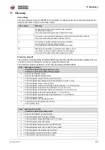
Class rating

The class rating according to DIN EN 61140 specifies the safety measures for electrical equipment to 

avoid electrocution. There are four class ratings:

Protection class IP

The protection class according to DIN EN 60529 indicates the suitability of electrical equipment for use 

in certain ambient conditions as well as the protection against risks.
The protection class is specified by an IP code according to DIN EN 60529.

Class rating

Meaning

0

No special protection apart from the basic insulation.

No grounded conductor.

Plug connection without grounded conductor contact.

I

Connection of all conductive housing components to the grounded conductor. 

Plug connection with grounded conductor contact.

II

Reinforced or double insulation (protective insulation).

No connection to the grounded conductor. 

Plug connection without grounded conductor contact.

III

Machines are operated on protective low voltage (< 50 V).

Connection to the grounded conductor is not necessary. 

Plug connection without grounded conductor contact.

Code

Meaning 1st number:
Protection against touching hazardous parts.
Protection against permeating foreign objects.

0

Not protected against contact.

Not protected against foreign bodies.

1

Protected against contact with the back of the hand.

Protected against large foreign objects with diameter > 50 mm (1.9 in).

2

Protected against contact with one finger.

Protected against medium-sized foreign objects (diameter > 12.5 mm (0.5 in)).

3

Protected against touch with a tool (diameter > 2.5 mm (0.01 in)).

Protected against small foreign objects with (diameter > 2.5 mm (0.01 in)).

4

Protected against touch with a wire (diameter > 1 mm (0.03 in)).

Protected against granular foreign objects (diameter > 1 mm (0.03 in)).

5

Protected against contact.

Protected against dust depositing inside.

6

Completely protected against any contact.

Protected from dust.

Code

Meaning 2nd number: 
Protection against permeating water

0

Not protected against permeating water.

1

Protected against water dropping vertically.

2

Protected against diagonally falling water (15° angle).

3

Protected against spray (60° angle).

4

Protected against spraying water from all directions.

5

Protected against water jets (nozzle) from any angle.

6

Protected against strong water jets (overflow).

7

Protected from temporary immersion in water.

8

Protected from ongoing immersion in water.

Summary of Contents for M1500

Page 1: ...Operator s manual Drive motor M1500 M2500 for modular internal vibrator HMS Model M1500 M2500 Document 5100020149 Issue 06 2015 Version 03 Language en...

Page 2: ...001 fm 2 Manufacturer Wacker Neuson Produktion GmbH Co KG Preu enstra e 41 80809 M nchen www wackerneuson com Tel 49 0 89 354 02 0 Fax 49 0 89 354 02 390 Translation of the original operator s manual...

Page 3: ...ors 14 3 9 Maintenance 14 4 General Power Tool Safety Warnings 15 5 Safety and information labels 18 6 Setup and function 19 6 1 Standard package 19 6 2 Application 19 6 3 Application area 19 6 4 Mode...

Page 4: ...lectrical and electronic equipment 36 15 Accessories 37 16 Technical data 38 16 1 Drive motor 38 16 2 Flexible shaft E optional 38 16 3 Flexible shaft S optional 39 16 4 Vibrator head standard optiona...

Page 5: ...in accordance with the information in this operator s manual It will reward your attention by providing you with a trouble free operation and high availability Defective machine parts must be replaced...

Page 6: ...at the time of printing Wacker Neuson reserves the right to make unannounced modifications to this information It must be ensured that possible modifications or supplements on the part of the manufact...

Page 7: ...pare parts and accessories that are not approved Improper handling Structural modifications of any kind Failure to observe the general terms and conditions GT C 2 9 Product identification of the machi...

Page 8: ...ering your safety and the safety of others Additionally the manufacturer s liability and warranty will be canceled In particular the following cases are considered structural changes Opening the devic...

Page 9: ...arts Using accessories that do not originate from Wacker Neuson Operator s manual Always keep the operator s manual readily available on the equipment or at the place of application of the equipment I...

Page 10: ...rk with the equipment when you are tired Perform all work calmly cautiously and carefully Never work under the influence of alcohol drugs or medication Your vision reactivity and judgment may be impai...

Page 11: ...o the following points Pay maximum attention near drops or slopes Risk of crashing No people may be in the working area Checks before starting work with the HMS Check the following points before start...

Page 12: ...ons and guidelines in order to keep the vibrations to a minimum You can find information about the vibration load of the HMS in the chapter Technical Data 3 6 Safety when operating hand held equipment...

Page 13: ...may only use tested extension cables that are suitable for construction site use Wacker Neuson recommends H07RN F H07BQ F a SOOW cable or a country specific equivalent design You must immediately rep...

Page 14: ...it is described in this operator s manual All other work such as the replacement of the power cable must be performed by the Wacker Neuson contact partner in order to avoid safety hazards You can find...

Page 15: ...tching outlets will reduce risk of electric shock b Avoid body contact with earthed or grounded surfaces such as pipes radiators ranges and refrigerators There is an increased risk of electric shock i...

Page 16: ...ed hazards n Do not let familiarity gained from frequent use of tools allow you to become complacent and ignore tool safety principles o A careless action can cause severe injury within a fraction of...

Page 17: ...working conditions and the work to be performed m Use of the power tool for operations different from those intended could result in a hazardous situation n Keep handles dry clean and free from oil a...

Page 18: ...e Replace missing or illegible labels The item numbers on the labels can be found in the parts book Item Label Description 1 Use personal protection equipment in order to avoid injuries and health haz...

Page 19: ...e combined HMS for the following activities Compaction of freshly mixed green concrete 6 4 Mode of operation Principle The drive motor drives the vibrator head via the flexible shaft which generates h...

Page 20: ...of the drive motor through the air cleaner element cools the electric motor and exits through the ventilation slots The airflow is represented by arrows in the drawing 7 2 Components of the HMS Depen...

Page 21: ...s of the flexible shaft optional 7 4 Components of the vibrator head optional Item Designation Item Designation 1 Connection to the drive motor 3 Bend protection 2 Coupling piece 4 Connection to vibra...

Page 22: ...r cable 3 Place the flexible shaft including the vibrator head in or on the suitable transport means as well 4 Secure all components against falling down or sliding away Shoulder strap for drive motor...

Page 23: ...ible shaft 1 Clamp the flexible shaft in a vise with prism jaws 2 Apply pipe thread seal to the thread of the flexible shaft 3 Place the vibrator head with the thread on the flexible shaft while inser...

Page 24: ...nt In the process the shaft core is received in the shaft core adapter of the drive motor 6 Release the t handle 7 Rotate the flexible shaft until the quick disconnect coupling locks into place 8 Pull...

Page 25: ...tional standards and guidelines 10 2 Commission Connect the HMS to the electric power supply WARNING Improper handling can lead to injuries or serious damage to property Read and observe all safety in...

Page 26: ...n hose off the ground to avoid damage to the equipment or the subgrade NOTICE Compact particularly intensely within the range of formwork corners because the spacing between the steel rods is the narr...

Page 27: ...ean all components of the HMS after every application 1 Clean the vibrator head and flexible shaft with water 2 Wipe down the drive motor and flexible shaft with a damp clean cloth 3 Clean the ventila...

Page 28: ...acle before all work on the equipment WARNING Risk of death from electric shock in the event of improper work According to the applicable guidelines opening the equipment repairing and a subsequent sa...

Page 29: ...head and protection hose with water Activity Daily before operation Every 50 hours Every 100 hours Every 300 hours Visual inspection of all elements for damage Check to ensure the connection links ar...

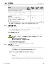
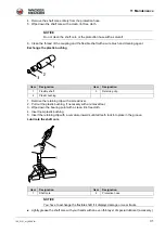
Page 30: ...element and ensure the correct fitting position 7 Insert the cover 8 Hand tighten the screw 11 3 3 Flexible shaft Remove the shaft core 1 Remove dirt accumulation within the range of the coupling 2 C...

Page 31: ...earing point with a clean lint free cloth 4 Insert new plastic bushing 5 Insert the retaining clip with a curvature inwards until all teeth lock into place in the groove Lubricate the shaft core Light...

Page 32: ...ench accessory 11 3 4 Vibrator head Check wear dimensions of the vibrator head The wear dimensions are Minimum diameter of vibrator head H vibrator head Minimum wrench size of the square HA vibrator h...

Page 33: ...y manner 2 Clean the thread of the fitting and the vibrator head with a wire brush and cleaning agent 3 Fill the oil in the housing to the suitable quantity according to the specifications see chapter...

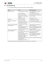
Page 34: ...lly but is overheating The filter element or air inlet is obstructed Remove the dirt exchange the filter element if necessary Too much special lubricant in the connected flexible shaft Remove excess s...

Page 35: ...or heads or excessively long flexible shafts overload the drive motor Excess wear and damage to the components is possible Only use permissible combinations of components Vibrator head Flexible shafts...

Page 36: ...ask the sales outlet about the proper disposal procedure for B2B electrical equipment in your country and ensure you dispose of the device in accordance with the valid legal guidelines Please also not...

Page 37: ...he flexible shaft With the special wrench you can disassemble the coupling of the flexible shaft more easily Pipe thread seal You need the pipe thread seal to seal the threaded connections between the...

Page 38: ...Typ A Type of engine Universal motor Universal motor Rated performance kW 1 50 1 80 Nominal speed min 1 rpm 11 500 11 500 12 000 12 000 Idle speed min 1 rpm 14 000 14 000 16 000 16 000 Protection clas...

Page 39: ...d Vibrator head diameter diagonal mm in 25 1 0 25 1 0 35 1 4 35 1 4 Length of vibrator head mm in 440 17 3 295 11 6 410 16 1 310 12 2 Weight kg lb 1 3 2 9 0 8 1 8 2 1 4 7 1 7 3 6 Oil specification Syn...

Page 40: ...15 0 405 15 9 390 15 4 395 15 6 Weight kg lb 1 3 2 8 2 3 5 1 3 3 7 3 3 9 8 6 Oil specification Synthetic oil Synthetic oil Synthetic oil Synthetic oil Oil quantity l 0 010 0 020 0 030 0 050 WARNING E...

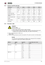
Page 41: ...xtension cable The equipment has 120 V input voltage According to the table your extension cable must have a stranded conductor cross section of 2 5 mm2 US Machine Machine Voltage V Extension ft Cross...

Page 42: ...st number Protection against touching hazardous parts Protection against permeating foreign objects 0 Not protected against contact Not protected against foreign bodies 1 Protected against contact wit...

Page 43: ......

Page 44: ......

Reviews: