MECHANICAL
Exterior Dimensions:
Model
A
B
C
D
A-130
510mm(20.0")
350mm(13.8")
290mm(11.5")
330mm(13.0")
A-550
635mm(25")
410mm(16.0")
400mm(15.8")
430mm(17.0")
A-1750
815mm(32")
545mm(21.5")
610mm(24")
535mm(21")
Internal Muffle Dimensions:
Model
E
F
G
A-130
120mm(4.6")
140mm(5.7")
130mm(5.2")
A-550
180mm(7.0")
230mm(9.0")
230mm(9.0")
A-1750
250mm(10.0")
360mm(14.0")
320mm(12.5")
Model
Furnace Weight:
Shipping Weight:
A-130
12kg(26lbs)
15kg(32lbs)
A-550
20kg(45lbs)
25kg(54lbs)
A-1750
44kg(97lbs)
60kg(132lbs)
8
5
OPERATIONS
STARTING OPERATION:
Close the furnace door. Turn the green power switch to the on (I) posi-
tion. The light inside the switch will turn on. An interlock door switch
located inside the furnace disconnects the power to the muffle when the
door is opened. The door must be closed for the furnace to heat.
Turn the setpoint knob to desired temperature and the furnace will ramp
to the set temperature. Turn off the power switch, to turn off the furnace.
The temperature rate will start out at full speed and gradually slow as it
approaches the setpoint temperature. If a slower temperature increase
rate is required set the temperature at several intermediate temperatures.
This will cause the control to approach each intermediate temperature at
a slower rate.
Note: Observe the rate curves on Pg.6-7 to determine the time required
to reach set-point.
OPERATING EXAMPLES:
The furnace will continuously operate at 900°C each day.
- Insert work, close door, adjust knob to 900°C (white inside scale).
- Turn power switch to on position (green light should come on when
door is down). If the same temperature is needed each day the knob
does not have to be adjusted.
- The furnace will heat to the temperature indicated on the front control
panel. Turn off the power switch when the cycle is finished.
A temperature cycle calls for a slow ramp to 700°C (1300°F).
Procedure:
- Insert work and close door.
- Turn power switch to on position (green light should come on when
door is down).
- Turn the set-point knob to 300°C (inside scale), 30 minutes later turn
the knob to 500°C, and finally 30 minutes later to 700°C .
- The furnace load slowly heats to the desired 700°C.
Note: Because of the nature of the control, the first 90% of the rate will
be relatively fast while the last 10% takes somewhat longer. The
furnace will reach the set point, but it takes some time. If a faster
rate is required, set the furnace to approximately 10 to 20% higher
than desired set-point and then adjust to the desired set-point when
temperature is reached.
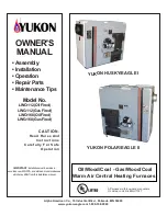
OUTLINE DRAWINGS mm(in)
A
B
D
C
E
F
G