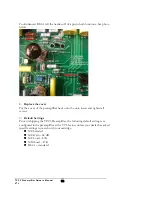
the screws from the top along the front and back edge. Carefully remove the cover
and the screws and store them in a safe place.
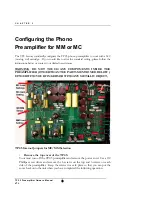
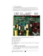
When you look down from the top, you will see a printed circuit board mounted inside
the preamplifier .
WARNING
:
DO NOT TOUCH ANYTHING INSIDE THE
PREAMPLIFIER, EITHER WITH YOUR FINGERS OR WITH ANY
METALLIC OBJECT, UNTIL AFTER THE UNIT HAS BEEN SAFELY
DISCHARGED
. The VTL preamplifiers can store energy in the power supplies long
after they have been turned off, and incorrectly discharging the unit can damage the
circuits, which will NOT be covered under the warranty. Be sure to understand these
constraints before going any further. If at this stage you feel that you would rather not
attempt this procedure yourself you can take the unit to your VTL Authorized Dealer
to have the work done.
If you feel comfortable with undertaking the procedure yourself then be sure to only
touch the tubes themselves, and do not allow any part of your body or hanging jewelry
to come into contact with any part of the circuit inside the unit.
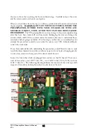
Locate the four tubes which are plugged into sockets on the PC board. There are a
total of four tubes, one 12AT7 tube (V2), two 12AX7 tubes (V101, V201) and one
12AU7 tube (V1). The following drawing indicates the location of the tube type with
respect to the sockets, looking from above and in front of the unit.
TP2.5 Preamplifier Owner’s Manual
VTL
14


