SCA3000 DEMO KIT
User Manual
3 Hardware
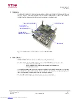
The CMA3000 DEMO KIT USB interface board (black PWB) and CMA3000 PWB (green PWB) are
shown in Figure 1. The USB interface card converts the USB interface to SPI or I
2
C interface.
CMA3000 sensor is soldered on PWB which is connected to interface board.
Figure 1. CMA3000 demo USB interface board and CMA3000 PWB.
Green led: data transfer
CMA3000 sensor
Test points for
CMA3000 sensor
Idd measurement
Red led: demo
powered from USB
Demo reset
4 GUI
software
CMA3000 DEMO KIT is controlled via USB serial port by GUI software.
The GUI software has four different display modes. The CMA3000 sensor can be set to:
-
normal measurement mode,
-
normal measurement mode with free fall detection enabled and
-
motion detection mode.
The interrupt detected due free fall or motion is indicated by led indicator and sound (if PC sounds
are enabled). Once interrupt is detected, the interrupt has to be cleared by user by pressing the red
led. The led appears on display only when the interrupt is detected.
The four different GUI displays and start up screens are presented below.
VTI Technologies Oy
4/21
www.vti.fi Doc.Nr.
8288400.02 Rev.0.2
electronic components distributor


