VTI CMA3000 User Manual Download Page 3


SCA3000 DEMO KIT 

User Manual 

 
VTI Technologies Oy 


3/21 

www.vti.fi Doc.Nr. 

8288400.02 Rev.0.2 


1 Introduction 

CMA3000 demo demonstrates the CMA3000 component functionality and the component key 
properties. This document describes how to install the required software and how to use the 
CMA3000 demo board and Graphical User Interface (GUI) software.  
 
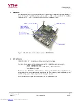
CMA3000 demo consists of: 


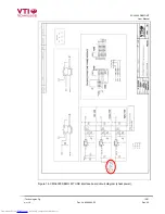
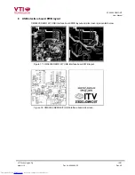
CMA3000 sensor soldered on chip carrier PWB (see Figure 1 on next page) 


USB interface card (see Figure 1 on next page) 

 USB 

cable 


GUI software running on PC 

 
The CMA3000 DEMO KIT supports digital CMA3000 series sensor, CMA3000-D01. The support 
for analog CMA3000-A01 will be added later. The evaluation boards (SCA3000 PWBs) are 
compatible with the SCA3000 DEMO KIT. 
 
CMA3000 demo runs on Windows XP and 2000, it requires USB connection for data transfer. 
Demo is powered from USB port. The current GUI software does not support Windows Vista. The 
CMA3000 demo is based on the same USB hardware PCB as the SCA3000 DEMO KIT, also the 
same driver can be used with all demo kits provided by VTI Technologies. 


Quick start for using the CMA3000 DEMO KIT 

Please follow the steps below: 

1. Insert 

CD-ROM 

2.  Setup the hardware 

Connect the demo kit to PC's USB port 

3.  Install the USB driver, after the PC has found the device 

When the PC detects the new USB device, do not let Windows to detect the driver, 
address the USB driver from folder:  

"CD-ROM\CMA3000 demo - Virtual Com Port Drivers\


-  NOTICE, if you have already installed some other demo kit provided by VTI 

Technologies, please check that the latency timer parameter is 5 ms. In case the 
latency timer value is greater than 5 ms, the CMA3000 DEMO KIT GUI will not 
work (more detailed instructions in section 9) 

4.  Install the GUI software  

Install the GUI software by running the “

setup.exe

" from folder: 

CD-ROM\CMA3000 demo – GUI Installer


Do not change the installation destination 

5.  Start the GUI software 

- From 

Start 

 Programs 

 CMA3000-USB-DEMO-VER-1.1 


CMA3000-USB-DEMO-VER-1.1 

 
When using the CMA3000 DEMO KIT with GUI software: 

  The DEMO KIT should be connected to PC before the GUI software is started 

  Exit the GUI software before unplugging the DEMO KIT from PC 

  After GUI software is stopped, the DEMO KIT can be unplugged from PC (DEMO KIT uses 

virtual serial port driver, so it can not be found as a USB device).  

 
During software start up, the firewall may alert that the demo software wants a network access. 
The demo software can be operated without the network access (granting the network access 
won't change the software operation.) 
 

Downloaded from 

Elcodis.com


electronic components distributor


Summary of Contents for CMA3000

Page 1: ...Doc Nr 8288400 02 CMA3000 DEMO KIT User Manual Downloaded from Elcodis com electronic components distributor ...

Page 2: ...10 5 Advanced data logging 10 6 CMA3000 current consumption measurement with DEMO KIT 12 7 USB interface board circuit diagram 13 8 USB interface board PWB layout 16 9 Troubleshooting 17 9 1 Checking and setting correct USB driver Latency timer value 18 9 2 Duplicate serial COM port numbers 20 9 3 Known Issues 21 9 3 1 Changing the serial bus type 21 10 Document Revision History 21 11 Contact Info...

Page 3: ...kit to PC s USB port 3 Install the USB driver after the PC has found the device When the PC detects the new USB device do not let Windows to detect the driver address the USB driver from folder CD ROM CMA3000 demo Virtual Com Port Drivers NOTICE if you have already installed some other demo kit provided by VTI Technologies please check that the latency timer parameter is 5 ms In case the latency t...

Page 4: ... is controlled via USB serial port by GUI software The GUI software has four different display modes The CMA3000 sensor can be set to normal measurement mode normal measurement mode with free fall detection enabled and motion detection mode The interrupt detected due free fall or motion is indicated by led indicator and sound if PC sounds are enabled Once interrupt is detected the interrupt has to...

Page 5: ...op the scrolling window Page Up button also 6 Open close the window extension with arrow button available only in SCROLL display 7 Pull down menu for acceleration g range Y axis 8 Manual Y axis range selections Manual setting has to be selected from Range pulldown menu 9 Current acceleration output value decimal display 10 Selected sensor type and GUI software version number 11 Averaging ON OFF nu...

Page 6: ...MA3000 D01 is selected by default Figure 4 Product selection pop up window SCROLL continuously scrolling X Y Z and resultant accelerations see Figure 5 Acceleration is presented in g User can change the acceleration scale freeze the scrolling image change the averaging factor set averaging OFF save acceleration data into file enable disable resultant scrolling select between sensor measurement ran...

Page 7: ... detection mode The transition from motion detection mode to normal measurement is presented in Figure 6 When motion is detected the operation mode is changed automatically to normal measurement mode Figure 6 Scroll display with detected motion BUBBLE LEVEL two displays that show tilt angle see Figure 7 Angle calculation is performed in GUI not in CMA3000 sensor CMA3000 sensor averaging can be ena...

Page 8: ...ging can be adjusted to smoothen the demo model movements Figure 8 3D demo display REGISTER CONFIG display offers user access in to CMA3000 sensor internal registers Registers can be read and written The written data format can be changed between binary and hexadecimal by pressing the Bits Hex button Figure 9 SCA3000 register configuration display Downloaded from Elcodis com electronic components ...

Page 9: ...is needed if the CMA3000 DEMO KIT is used without the GUI software see further details from section 5 In this example the CMA3000 DEMO KIT uses COM39 serial port Figure 10 Setup display RESET DEMO initialises the GUI software The embedded MCU software version is presented also SCROLL display opens after RESET by default Figure 11 Reset demo display VTI Technologies Oy 9 21 www vti fi Doc Nr 828840...

Page 10: ...ction ht or see detailed serial communication settings in Table 2 5 Press demo reset button see Figure 1 CMA3000 DEMO KIT sends an info text to HyperTerminal see Figure 12 If the HyperTerminal software is unable to connect the CMA3000 DEMO KIT or the info text does not appear Press disconnect change the COM port number to correct from port properties press connect press reset button on CMA3000 DEM...

Page 11: ...ons HyperTerminal The communication settings are presented in Table 2 below Table 2 CMA3000 DEMO KIT serial communication settings Connection properties 2 Connect 1 Select COM port Figure 12 Windows HyperTerminal with CMA3000 demo info text Parameter Value Bits per second 230400 Data bits 8 Parity None Stop bits 1 Flow control None The correct COM port number depends on the PC and used USB port Do...

Page 12: ... can also be measured by measuring the voltage drop over the resistor R34 TP5 and TP6 see Figure 16 when CMA3000 PWB is not connected to USB interface board SCA3000 current consumption can be calculated 470 Ω offset drop V V Idd 1 where Vdrop is the measured voltage drop in V from TP5 to TP6 see Figure 16 Voffset is the measured offset current consumption from TP5 to TP6 see Figure 16 alternativel...

Page 13: ...00 demo USB interface board circuit diagram is presented in following pages Figure 14 CMA3000 DEMO KIT USB interface board circuit diagram sheet USB VTI Technologies Oy 13 21 www vti fi Doc Nr 8288400 02 Rev 0 2 Downloaded from Elcodis com electronic components distributor ...

Page 14: ... KIT User Manual VTI Technologies Oy 14 21 www vti fi Doc Nr 8288400 02 Rev 0 2 Figure 15 CMA3000 DEMO KIT USB interface board circuit diagram sheet MCU Downloaded from Elcodis com electronic components distributor ...

Page 15: ...KIT User Manual VTI Technologies Oy 15 21 www vti fi Doc Nr 8288400 02 Rev 0 2 Figure 16 CMA3000 DEMO KIT USB interface board circuit diagram sheet power Downloaded from Elcodis com electronic components distributor ...

Page 16: ...e board PWB layout and silkscreen is presented below Figure 17 CMA3000 DEMO KIT USB interface board PWB layout Figure 18 CMA3000 DEMO KIT USB interface board silkscreen VTI Technologies Oy 16 21 www vti fi Doc Nr 8288400 02 Rev 0 2 Downloaded from Elcodis com electronic components distributor ...

Page 17: ...ndow check that USB driver LATENCY TIMER parameter is 5ms please see details in section 9 1 5 Some times other LabView based software do not allow the demo kit GUI software execution please try to install the CMA3000 demo kit to another PC or remove other LabView based software 6 If the PC is unable to find the demo kit serial port try another USB port Also please check that there are not duplicat...

Page 18: ...k properly In order to modify the driver s Latency timer value please plug the demo USB cable in to PC and follow the steps and screen captures below 1 Open control panel and select SYSTEM 2 Select DEVICE MANAGER from HARDWARE tab 3 Select USB SERIAL PORT from the list right mouse click and select PROPERTIES 4 Select ADVANVED from the USB Serial port Properties 5 Set the LATENCY TIMER to 5 ms the ...

Page 19: ...SCA3000 DEMO KIT User Manual 5 4 3 VTI Technologies Oy 19 21 www vti fi Doc Nr 8288400 02 Rev 0 2 Downloaded from Elcodis com electronic components distributor ...

Page 20: ...anagement Device Manager see section 9 1 for instructions on opening the Device Manager PC installs the demo kit on same COM port number as another device After changing the demo to another USB port different slot there are no duplicate COM port numbers Figure 19 PC has assigned duplicate COM port numbers for two devices LEFT after changing the USB port there are no duplicate COM port numbers RIGH...

Page 21: ... fi Germany VTI Technologies Oy Branch Office Frankfurt Rennbahnstrasse 72 74 D 60528 Frankfurt am Main Germany Tel 49 69 6786 880 Fax 49 69 6786 8829 E mail sales de vti fi USA VTI Technologies Inc One Park Lane Blvd Suite 804 East Tower Dearborn MI 48126 USA Tel 1 313 425 0850 Fax 1 313 425 0860 E mail sales vtitechnologies com Japan VTI Technologies Oy Tokyo Office Tokyo to Minato ku 2 7 16 Bur...

Reviews: