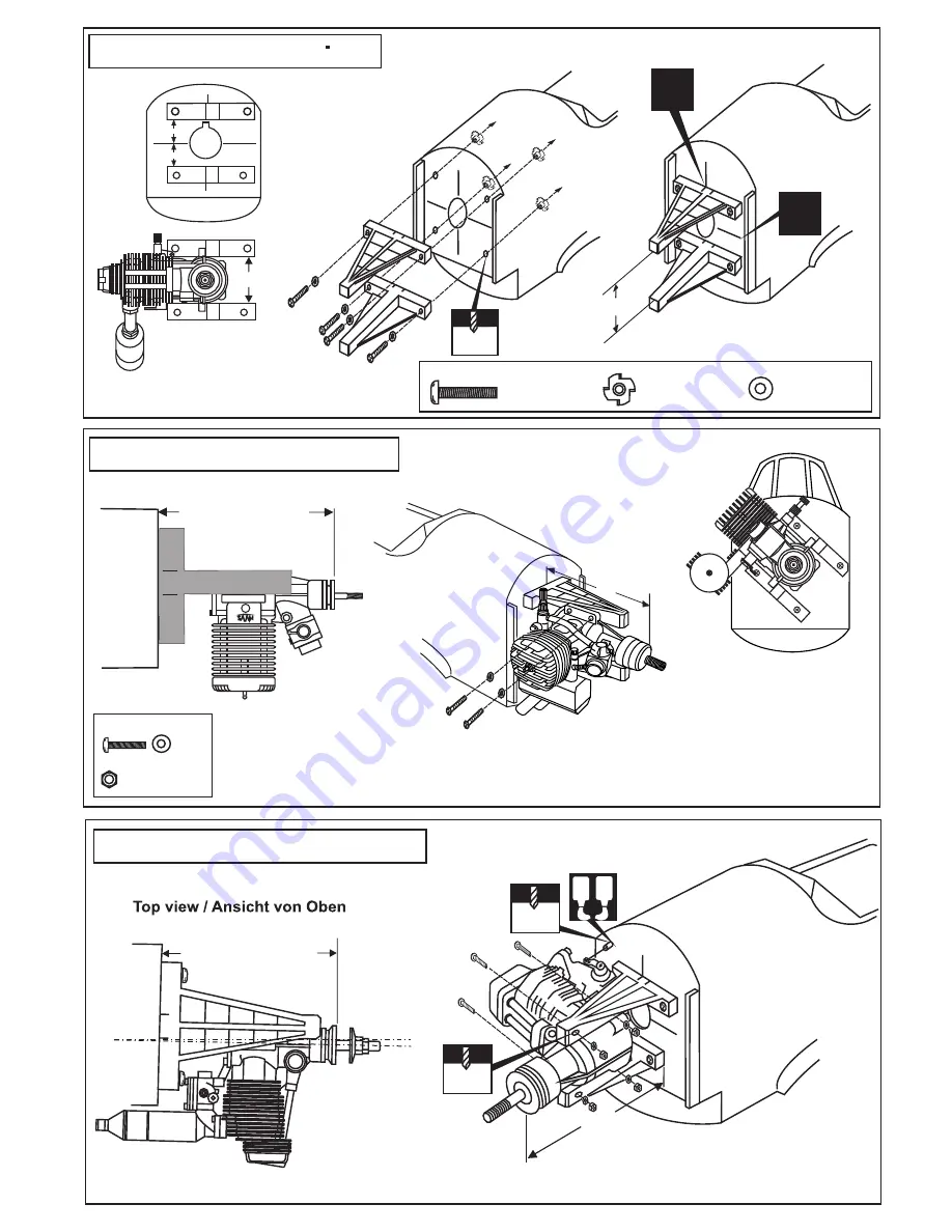
VQ VQA016 Instruction Manual Download Page 9

A B

A

3.mm

! Engine thrust on balk head
  is already adjust at factory

......4

............4

4x25mm screw

Blind-nut

4mm washer

.................4

116~119mm

!

! Engine thrust on balk head
  is already adjust at factory

! Align the mark on both mounts 
with the center mark on the fire wall

! Align the engine 
center with fire wall 
marked line

!

5mm

13/64”

18- Engine  (four stroke) / 4T Motor

1/8

3mm

1/8

4.5~4.7”

(116~119mm)

A

A

Determine the angle for 
the engine mounts so the
muffler will not contact the 
fuselage

17- Engine (two stroke) / 2T Motor

6.5

With hang silencer

With side silencer

(116~119mm)

B=B’

A

FRONT-VIEW

B

B’

A

B

B’

3x25mm screw

Nut

.............4

...4

A

 4-19/32” ~ 4-23/32”

16- Engine mount / Motortrager

Summary of Contents for VQA016

Page 1: ...al advice if you are unexperienced ACHTUNG Dieses ferngesteuerte Modell ist KEIN Spielzeug Es ist f r fortgeschrittene Modellflugpiloten bestimmt die ausreichende Erfahrung im Umgang mit derartigen Mo...

Page 2: ...hol Drill and Assorted Drill Bits Read through the manual before you begin so you will have an overall idea of what to do Symbols used throughout this instruction manual comprise Purchase separately R...

Page 3: ...y into the wing joiner cavity of one wing half 6 Coat one half of the dihedral brace with epoxy up to the center line Install the epoxy coated side of the dihedral brace into the wing joiner cavity up...

Page 4: ...rvo arm a small piece of masking tape works well for this Cut off the excess length each rod Cut away only the covering 4 Servo mount Servohalterung A FWU2 FWU1 A CENTER WING SECTION CA CA CA CA BOTTO...

Page 5: ...IC RETRACT LANDING GEAR 8 Electric retract landing gear Einziehfahrwerk RECEIVER ON OFF GEAR ELECTRIC RETRACT LANDING GEAR EXTENDED POSITION RETRACTED POSITION Ply gear mount plate x 2 Gear mount x 2...

Page 6: ...of the stabilizer where it meets the fuselage 2 Remove the horizontal stabilizer from the fuselage Using the sharp hobby knife carefully cut away the covering inside the lines which were marked above...

Page 7: ...er A B Apply the epoxy both side Apply a thin layer of machine oil or petroleum jelly to only the pivot point of the hinges on the elevator then push the elevator and its hinges into the hinge slots i...

Page 8: ...inum motor mounting plate and drill a 1 8 3mm hole through the plywood at each of the four marks marked 4 3mm 1 8 1 2 3 4 Plywood motor mounting plate 2pcs Aluminum motor mounting plate Firewall B B B...

Page 9: ...ter mark on the fire wall Align the engine center with fire wall marked line 5mm 13 64 18 Engine four stroke 4T Motor 1 8 3mm 1 8 4 5 4 7 116 119mm A A Determine the angle for the engine mounts so the...

Page 10: ...he board or transparent plastic for the engine head as marked above Remove the engine and insert the cowl on to the fuselage so the distance from the fire wall to the front of the cowl is 4 33 64 to 4...

Page 11: ...battery pack to achieve this C G location A or 5mm is fine Bottom view Ansicht von unten Connector Connector 1 3 Gestangeanschluss Gestangeanschluss Rudergestange Rudergestange Drosselservo Seitenrude...

Page 12: ...cess that is produced Adjust the engine always from behind but never from infront or the sides as rotating propeller may badly injure you Do not allow watching people to get too close to a rotating pr...

Reviews: