VQ VQA016 Instruction Manual Download Page 7

Cut away only
the covering 
both side

B = B’
C = C’

B

B’

C

C’

A B

Apply the epoxy
both side

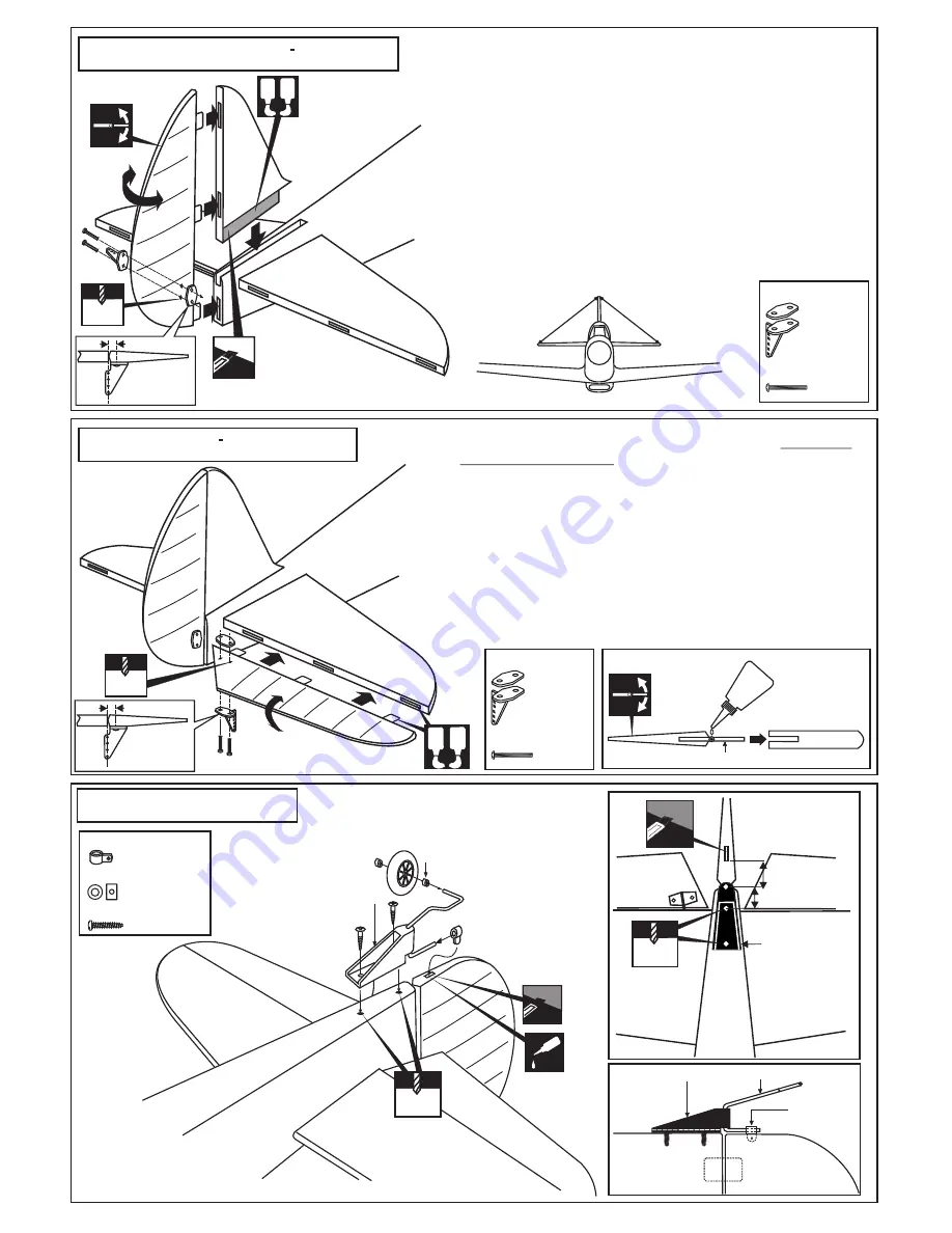
1-Trial fit the vertical stabilizer in place . Check the alignment of the 
   vertical stabilizer. When you are satisfied with the alignment, use a 
   pencil to trace around the right and left of the stabilizer where it 
   meets the fuselage.
2-Remove the vertical stabilizer from the fuselage. Using the sharp 
   hobby knife, carefully cut away the covering inside the lines which 
   were marked above.
3-Spread epoxy (30 minute) onto the right and left and bottom of the 
   vertical stabilizer along the area where the covering was removed 
   and to the fuselage where the vertical stabilizer mounts.

4-Install the vertical stabilizer into the fuselage and adust the align-
   ment as described in steep 1
5-Wipe off any excess epoxy using a paper towel and rubbing alcohol
   Allow the epoxy to cure before proceeding to next step.

13- Elevator / Hohenruder

A B

Apply the epoxy both side

Apply a thin layer of machine oil or petroleum jelly to only the 
pivot point of the hinges on the elevator, then push the elevator 
and its hinges into the hinge slots in the trailing edge of the
horizontal stabilizer. 
When satisfied with the and alignment, hinge the elevator to 
the horizontal stabilizer using 5 minute epoxy. Make sure to 
apply a thin layer of epoxy to the top and bottom of both hinges 
and to inside the hinge slots. Repeat the previous procedures
to hinge the second elevator to the other side of the horizontal 
stabilizer    

Hinge

Petroleum jelly

5/16”(8mm)

12~15mm

1.5mm

1/16

½~5/8”

CA

3x12mm screw

Collar

Tail gear mount

Horn

Horn

Tail wheel mount

Fuselage

Rudder

Gear

NOTE: Check the wheel turns freely.

Piece of fuel tube (not included)

Side view

14- Tail gear / Spornrad

Control horn

................2

2x12mm screw

..........4

Control horn

................1

2x12mm screw

..........2

2.mm

5/64”

2.mm

5/64”

2.mm

5/64”

STABILIZER

Horn

2.2m collar

3x12mm screw

.................1

................1

...............2

3/8” (10mm)

12- Vertical stabilizer / Hohenleitwerk

Elev.

Stab.

3/8” (10mm)

Elev.

Stab.

Bottom view / Ansicht von unten

Bottom view 
Ansicht von unten

Tail gear mount

Summary of Contents for VQA016

Page 1: ...al advice if you are unexperienced ACHTUNG Dieses ferngesteuerte Modell ist KEIN Spielzeug Es ist f r fortgeschrittene Modellflugpiloten bestimmt die ausreichende Erfahrung im Umgang mit derartigen Mo...

Page 2: ...hol Drill and Assorted Drill Bits Read through the manual before you begin so you will have an overall idea of what to do Symbols used throughout this instruction manual comprise Purchase separately R...

Page 3: ...y into the wing joiner cavity of one wing half 6 Coat one half of the dihedral brace with epoxy up to the center line Install the epoxy coated side of the dihedral brace into the wing joiner cavity up...

Page 4: ...rvo arm a small piece of masking tape works well for this Cut off the excess length each rod Cut away only the covering 4 Servo mount Servohalterung A FWU2 FWU1 A CENTER WING SECTION CA CA CA CA BOTTO...

Page 5: ...IC RETRACT LANDING GEAR 8 Electric retract landing gear Einziehfahrwerk RECEIVER ON OFF GEAR ELECTRIC RETRACT LANDING GEAR EXTENDED POSITION RETRACTED POSITION Ply gear mount plate x 2 Gear mount x 2...

Page 6: ...of the stabilizer where it meets the fuselage 2 Remove the horizontal stabilizer from the fuselage Using the sharp hobby knife carefully cut away the covering inside the lines which were marked above...

Page 7: ...er A B Apply the epoxy both side Apply a thin layer of machine oil or petroleum jelly to only the pivot point of the hinges on the elevator then push the elevator and its hinges into the hinge slots i...

Page 8: ...inum motor mounting plate and drill a 1 8 3mm hole through the plywood at each of the four marks marked 4 3mm 1 8 1 2 3 4 Plywood motor mounting plate 2pcs Aluminum motor mounting plate Firewall B B B...

Page 9: ...ter mark on the fire wall Align the engine center with fire wall marked line 5mm 13 64 18 Engine four stroke 4T Motor 1 8 3mm 1 8 4 5 4 7 116 119mm A A Determine the angle for the engine mounts so the...

Page 10: ...he board or transparent plastic for the engine head as marked above Remove the engine and insert the cowl on to the fuselage so the distance from the fire wall to the front of the cowl is 4 33 64 to 4...

Page 11: ...battery pack to achieve this C G location A or 5mm is fine Bottom view Ansicht von unten Connector Connector 1 3 Gestangeanschluss Gestangeanschluss Rudergestange Rudergestange Drosselservo Seitenrude...

Page 12: ...cess that is produced Adjust the engine always from behind but never from infront or the sides as rotating propeller may badly injure you Do not allow watching people to get too close to a rotating pr...

Reviews: