- 4 -
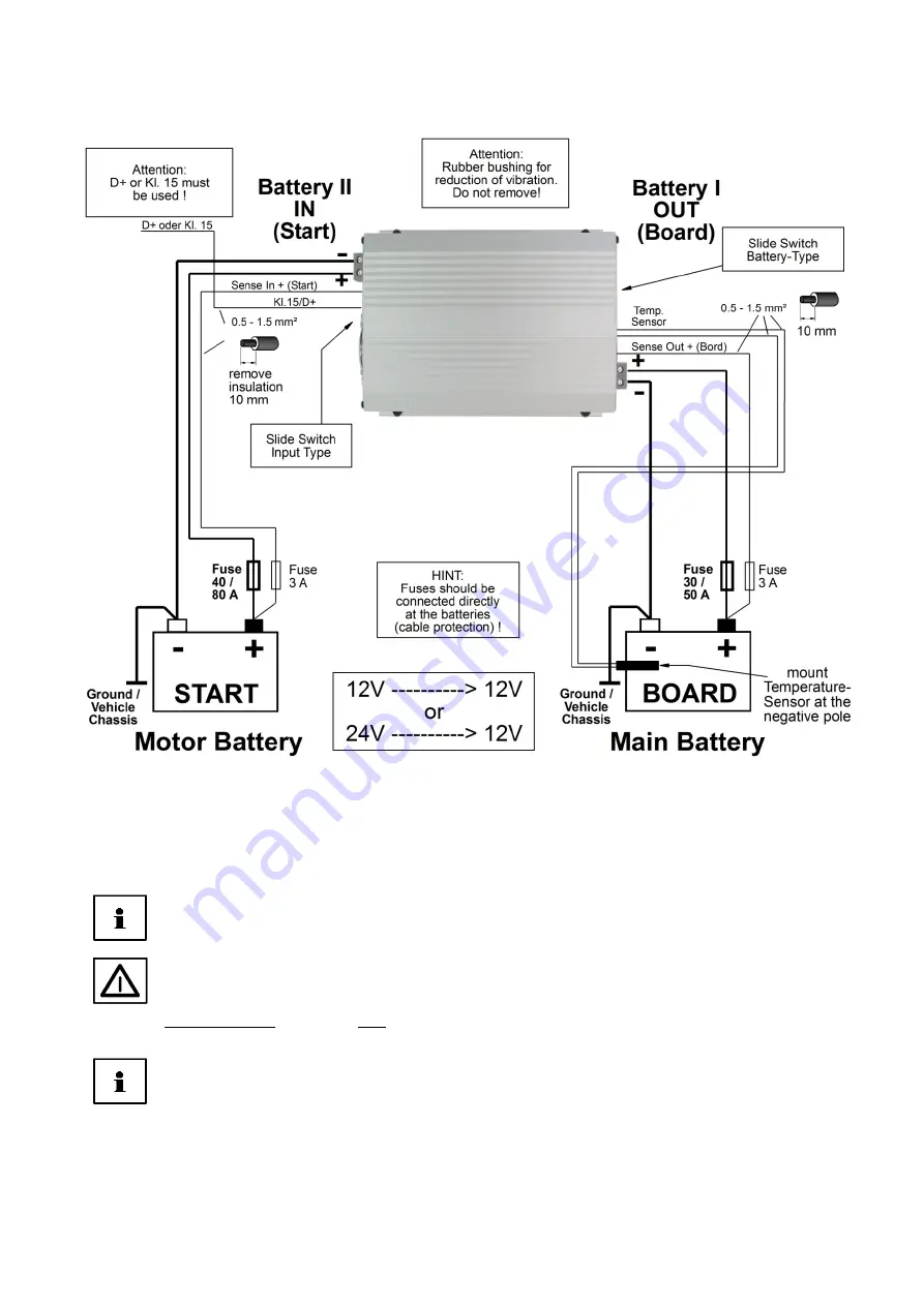
General Connection Plan Charging Converter, All Types:
Note:
For safety reasons, the unit does not operate, unless the
temperature sensor
had been
connected! The temperature sensor must be screwed-down to the negative pole of the
battery.
If possible, the unit should always be installed
as close as possible
to the
board battery I
.
Observe the cable cross-sections, lengths and fuses according to the table on page 5!
Possibly existing cables, which do not have the required cross-sections must be adapted to the
minimum requirements in any case!
Reverse battery (+/-) at the IN II (Start) side will result in serious damage of the unit!
Input and output side
of the charging converter are separated
by galvanic isolation,
i. e. there is no
conductive connection
between the input II (START) side and the output I side (BOARD).
Thus, the two battery circuits are completely independent of each other, and a mutual influence or
disturbance is avoided.
Therefore, the
minus
(
-
) terminals
I
and
II
must imperatively be connected observing the indicated cable
cross-sections. Refer to connection plan.
If required, the two sensor lines "Sense In +" and "+ Sense Out" (see table2) must be led
separately
and as
separate line
to the
+ poles of the battery!
This is the only way to achieve a correct voltage measurement
at the batteries. The sensor lines near the battery must be protected with a fuse (cable protection)!


