Typical application
Fig. 2 ÷ 5;
Fig. 5: A= inlet; B= outlet
NOTE
The appliance’s inlet and outlet ports must always be
connected to a suitable duct.
Installation
Fig. 6 ÷14.
NOTE
Use of the supplied brackets is optional.
Function
Figs. 15 ÷20.
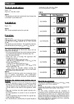
The appliance leaves the factory with Minimum (Vmin)
and Maximum (Vmax) speeds set at their nominal
values.
The electronic board fitted to the appliance has two
potentiometers for setting Vmin and Vmax (fig.15).
Pre-set speed changes (set by installer)
Any initial adjustment of Vmin and Vmax can be
carried out as follows:
- Turn the potentiometers fully anti-clockwise before
connecting the appliance to the mains (fig. 16);
- turn the appliance ON;
- within one hour of turning the appliance ON,
proceed as follows:
* position the external switch at Vmin ;
* use the Vmin potentiometer to set Vmin at the
desired speed; (fig .17)
* position the external switch at Vmax;
* use the Vmax potentiometer to set Vmax at the
desired speed (fig. 18).
* wait about 10 minutes before turning the
appliance off to allow the system time to memorise
the speeds that have been set.
NOTE:
Only adjust the trimmer using non-conductive tools
(e.g.
a
plastic
screwdriver).
Any
subsequent
adjustments can be made using the same sequence
as above.
Restoring the original speed settings (set by
installer)
- With the appliance turned off, change the original
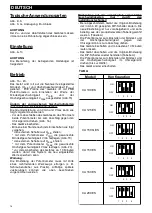
settings of the dip-switches shown in fig 20. The
new setting will only be temporary and can be any
of those shown in the table for this appliance. (table
A)
- Fully turn the Max and Min speed adjuster anti-
clockwise.
- Turn the appliance on and let it run for at least 10
minutes.
- Turn the appliance off and restore the original dip-
switch settings (table A).
- Turn the Minimum and Maximum speed adjusters
clockwise to the half-way stage.
- Turn the appliance on again.
Select the pre-set speeds
The user can change between Vmin and Vmax using
an external switch (not supplied)
NOTE
Increasing the speed of the motor leads to greater
power consumption and higher noise levels.
NOTE
CA
ES
series
products
can
be
operated
in
conjunction with environmental sensors and timers
that switch the products on at a preset speed when
certain thresholds are reached e.g. Relative Humidity
(C HCS), Temperature (C TEMP), Smoke (C Smoke), if
the vicinity detector is activated (C Pir) or while the
Timer is being set (C Timer).
10
ENGLISH
Model
CA 100 ES
CA 125 ES
CA 150 Q ES
ON
OFF
1 2 3 4
ON
OFF
1
2 3 4
ON
OFF
1 2 3 4
Configuration
TAB A
CA 150 ES
CA 160 ES
CA 200 ES
ON
OFF
1 2 3 4
ON
OFF
1
2 3 4
ON
OFF
1 2 3 4
Summary of Contents for CA 100 ES
Page 61: ...61 4 4 5 5 6 6 CA 100 125 150Q ES CA 150 160 200 ES 7 7 CA 100 125 150Q ES CA 150 160 200 ES ...
Page 62: ...62 8 8 CA 100 125 150Q CA 150 160 200 ES 9 9 CA 100 125 150Q ES CA 150 160 200 ES 10 10 11 11 ...
Page 63: ...63 12 12 13 13 14 14 13A 13A 14A 14A ...
Page 64: ...64 17 17 MIN 18 18 MAX 19 19 15 15 MAX MIN 16 16 MIN MAX ...
Page 66: ...66 24 24 25 25 26 26 ...
Page 67: ...67 Note ...


