background image

16

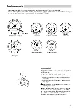
Instruments

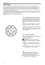
Alarm display

provides you with a visual warning, if and when an alarm occurs, to notify you of an existing malfunction.

The warning lamps light up, in sequence, when the starter key is first turned to the drive position and right after
the engine has been started. Check that all lamps function and that they go out once the engine is started.

If a fault occurs the associated lamp on the alarm display will light up, the Tachometer/LCD display will show an
alarm warning and the alarm buzzer sound.

The alarm buzzer will only go on the first time a fault is detected. If the fault disappear and then come back again,
only the lights will come on (ex. the coolant temperature goes down and then back up). Exception is the depth
alarm that will sound every time the fault is detected.

NOTE!

 Warning lamps should never light up during operation.

General Warning (red or yellow indication)

The "General Warning lamp" will light up at any fault,
including EVC system faults, single or together with an
other alarm lamp. Additionally, the LCD screen dis-
plays a more specific alarm warning and the buzzer
sounds.

Red: 

for faults requiring immediate action or attention

by the operator. The buzzer will sound constantly.

Yellow:

 for less critical faults that are not necessarily

cause for immediate concern, but may result in loss of
performance or funtionality. The buzzer will sound with
three short beeps.

Oil pressure (red indication) 

If the oil pressure lamp lights up during operation, the oil
pressure in the engine is too low.

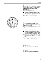
Stop the engine at once.


WARNING

!  Continued operation when the oil

pressure is too low can cause serious engine dam-
age.

Check the oil level in the engine. Please refer to
“Maintenance: Lubrication system” to check and top
the oil up.

Also check that the oil filter is not blocked. Please
refer to “Maintenance: Lubrication system”


Water in fuel filter (orange indication)

If the water in fuel lamp lights up, there is too much
water in the water trap in the fuel pre-filter.

Empty the water trap underneath the fuel pre-filter.
Please refer to “In case of emergency”.

Summary of Contents for D3-110i-A

Page 1: ...OPERATOR SMANUAL D3 130A A D3 160A A D3 110i A D3 130i A D3 160i A ...

Page 2: ... instruktionsboken kan bestäl las på svenska Beställningskupong finns i slutet av instrukti onsboken Questo manuale d istruzioni può esse re ordinato in lingua italiana Il tagliando per l ordinazione è riportato alla fine del manuale Dit instructieboek kan worden besteld in het Nederlands De bestelcoupon vindt u achter in het instruc tieboek Denne instruktionsbog kan bestilles på dansk Bestillings...

Page 3: ...nce and long service life We also believe that this is what you demand and expect of your Volvo Penta engine We would like you to read this operator s manual thoroughly and consider the advice we give on running and maintenance before you cast off on your maiden voyage so that you will be ensured of fulfilling your expectations With warm regards AB VOLVO PENTA IMPORTANT These instructions do not c...

Page 4: ...erunning 41 Alarm 42 Runningaground 43 Stopping the engine 44 45 Stopping 44 After stopping 44 Coldweatherprecautions 45 Operationbreak 45 Transporting on a trailer 45 In case of emergency 46 48 Starting using auxiliary batteries 46 Emergency shifting 47 Water in fuel 47 Fault tracing 48 Diagnostic function 49 LCDAlarmWarning 50 Maintenanceschedule 51 52 Maintenance 53 84 Engine general 53 Lubrica...

Page 5: ...nta dealer for assistance This symbol is used in the book and on the engine to make you aware of safety information Always read these safety precautions very carefully In the operator s manual warning texts have the following priority WARNING If these instructions are not followed there is a danger of personal injury exten sive damage to the product or serious mechanical malfunction IMPORTANT Used...

Page 6: ...ng the boat after the engine has been stopped This will help you to quickly detect fuel coolant or oil leaks and spot anything else unusual that has or is about to hap pen Maneuvering Avoid violent and unexpected changes in course and gear engagement This could cause someone on the boat to lose their balance and fall over or overboard A rotating propeller can cause serious injury Check that nobody...

Page 7: ...the cover as well Get in touch with your boat dealer for help in obtaining the best solution for your boat Checklist Safety equipment Life jackets for all passengers communication equipment emergency rockets approved fire extinguisher first aid equipment life belt anchor paddle torch etc Replacement parts and tools impeller fuel filters fuses tape hose clamps engine oil propeller and tools for any...

Page 8: ...ever carry out work on an engine suspended on a hoist Beforestartingtheengine Reinstall all protective parts removed during service operations before starting the engine Check that no tools or other items have been left on the engine Never start a turbocharged engine without installing the air cleaner ACL The rotating compressor in the Turbocharger unit can cause serious personal injury Foreign ob...

Page 9: ...open or a coolant hose disconnected open the cool ant filler cap carefully and slowly to release pressure before removing the cap completely Note that the coolant may still be hot and can cause burns Lubrication system Hot oil can cause burns Avoid skin contact with hot oil Ensure that the lubrication system is not under pressure before commencing work on it Never start or operate the engine with ...

Page 10: ...them Remember to always leave hazardous waste such as waste oil coolant paint and wash residue flat batteries etc for disposal at a de struction plant Our joint efforts will make a valuable contribution to our environment Running in The engine must be run in for its first 10 operating hours as follows Operate the engine normally Do not operate it at full load except for short periods Never run the...

Page 11: ...ines manufactured of that type correspond to the certified engine This places special requirements for maintenance and service as follows The maintenance and service intervals recom mended by Volvo Penta must be observed Only genuine Volvo Penta replacement parts may be used The service of injection pumps and injectors or pump settings must always be carried out by an authorized Volvo Penta worksh...

Page 12: ...tore the information so that it is available in event of the boat being stolen NOTE Install the appropiate sticker from shield and drive onto the warranty decal Engine Product designation 1 Serial number 2 Product number 3 Drive Product designation 4 Gear ratio 5 Serial number 6 Product number 7 Introduction Shield Drive Product designation 8 Serial number 9 Product number 10 The numbers refer to ...

Page 13: ...y iron cylinder liners Six bearing crankshaft Engine mounting Flexible engine mounting Lubrication system Easily replaceable insert separate full flow oil filter Plate oil cooler Fuel system Common rail injection system Control unit for processing the injection Fine filter with water separator Emergency stop device Air inlet and exhaust system Air filter with replaceable insert Closed crankcase ve...

Page 14: ...p engine 5 Heatexchanger 6 Oil cooler 7 Oil dipstick engine 8 Fuel filter 9 High pressure fuel pump 10 Alternator 11 Seawaterpump 12 Oil filter 13 Chargeaircooler CAC 14 Oil filler SX 15 Trim cylinder SX 16 Oil dipstick SX 17 Sacrificial anode SX 18 Oil draining SX 6 5 3 4 2 1 14 15 17 16 18 7 8 9 11 10 12 13 ...

Page 15: ...lant filler cap 4 Oil filler cap engine 5 Heatexchanger 6 Oil cooler 7 Oil dipstick engine 8 Fuel filter 9 High pressure fuel pump 10 Alternator 11 Seawaterpump 12 Oil filter 13 Chargeaircooler CAC 14 Oil filter reverse gear 15 Oil cooler reverse gear 16 Oil dipstick reverse gear 14 3 4 2 1 6 5 15 ...

Page 16: ... control panel as well as via the usual gauges and alarm buzzer At the touch of a button the operator may view various informa tion provided by the system or may make a number of changes to the way in which information is displayed Benefits of Using the EVC System There are many benefits to having EVC installed on a boat the most important of which is safety EVC ensures that your boat s systems ar...

Page 17: ...he key can be inserted and taken out 1 Operating and running position System voltage connected 2 Starter position spring loaded The starter motor is engaged IMPORTANT Read the starting instructions in Starting the engine NOTE The ignition keys are marked with a key code used when ordering extra keys Make a note of this key code so that keys can be ordered if the old keys get lost Keep the code in ...

Page 18: ...y fault including EVC system faults single or together with an other alarm lamp Additionally the LCD screen dis plays a more specific alarm warning and the buzzer sounds Red for faults requiring immediate action or attention by the operator The buzzer will sound constantly Yellow for less critical faults that are not necessarily cause for immediate concern but may result in loss of performance or ...

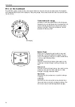
Page 19: ... The coolant temperature lamp lights up when the cool ant temperature is too high Stop the engine if this lamp lights up during opera tion Check the coolant level Please refer to Mainte nance Freshwater system WARNING Do not open the coolant filler cap when the engine is warmcould cause serious en gine damage Steam or hot fluid could spray out Check that the sea water filter if installed is not bl...

Page 20: ...tem Button Panel allows you to navigate through the EVC menus and submenus on the Tachometer LCD display The but tons on this panel also allow you to make modifications to various user defined settings Up Arrow Used to scroll up through menus Also used in some submenus to make changes to settings increase val ues Down Arrow Used to scroll down through menus Also used in some submenus Also used in ...

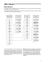
Page 21: ...lled some of the screens described in the following section may not be available on your LCD screen If you feel that the specific installation on your boat should allow you to access screens that are not displayed please con sult your dealer to determine if there is an error with the installation Menu System Menu Structure The EVC MC system is controlled via a button panel located on the boat s co...

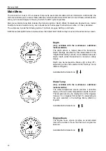
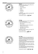
Page 22: ...n Some of these submenus also allow you to make changes to the way in which the EVC system operates Main menu informational data includes the following options Depth Water Temperature Engine Hours Instant Fuel Rate Instant Fuel Economy and a Faults menu that displays the fault status when or if one is detected The submenus include the following options Trip Data Gauges Settings and Faults Each men...

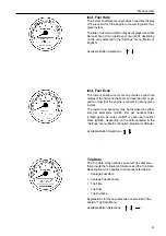
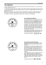
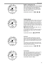
Page 23: ...n of fuel that the engine is consuming at any given instant The instant fuel economy may be displayed as either liter per kilometers L KM liter per nautical miles L NM gallon per miles G MP or gallon per nautical miles G NM depending on the units selected in the Settings menu Metric or English Nautical or Statute Available Button Selections Trip Data The Trip Data screen allows you enter Trip subm...

Page 24: ...ns for these submenus are provided in the section Settings Menu Available Button Selections No Faults The No Faults screen is where system faults are dis played when or if a fault occurs When the EVC sys tem detects a new fault the alarm will sound and the display will automatically switch to show the newest fault in the Faults submenu The letters AL will blink in the upper left corner of the scre...

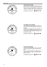
Page 25: ...f you reset the display the first reading will be the last instant fuel rate reported by the engine Assuming you maintain speed this value will remain constant If you vary the boat s speed over time the fuel rate will increase or decrease to reflect the chang ing rate of fuel consumption Average fuel rate is displayed as either liters per hour L H or gallons per hour G H depending on the units sel...

Page 26: ... dis tance the boat has travelled since you last reset the trip data Trip distance is displayed as nautical miles NM stat ute miles MI or kilometers KM depending on the units selected in the Settings Menu Nautical or Stat ute Metric or English Available Button Selections Trip Fuel Trip Reset The Trip Fuel screen displays the amount of fuel the engine has consumed since you last reset the trip data...

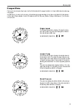
Page 27: ...lu tions per Minute RPM only Available Button Selections Coolant Temp The Coolant Temp menu displays the temperature of the engine coolant The value displayed may vary by engine type and coolant method i e raw water cooled or closed cooling system Please refer to Operation Reading the instruments for normal operating parame ters The units are displayed as degrees Celsius o C or de grees Fahrenheit...

Page 28: ...ount of angle on your transom and other variables the trim level val ue may actually be outside the range above Your deal er can tell you if the value being displayed is correct for your boat NOTE If you are using an inboard engine the Trim Po sition gauge will not be displayed on the Tachometer LCD NOTE For a detailed explanation of using the trim switches and trim position for your drive please ...

Page 29: ...remaining in the fuel tank The units are displayed as a percentage of the full fuel level A full tank is represented as 100 If you ve used a quarter tank of fuel the gauge shows 75 half a tank shows 50 a quarter tank remaining is dis played as 25 and so on Available Button Selections ...

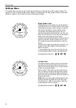
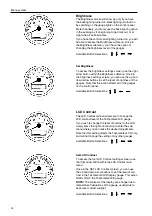
Page 30: ...th for 5 seconds When the alarm sounds it can be cancelled by pressing the left button as with any alarms The units are displayed as meters M or feet FT de pending on the units selected in the Settings Menu Metric or English To change this setting press the right arrow to move into the Set Depth Alarm submenu described below Available Button Selections Set Depth Alarm The Set Depth Alarm submenu a...

Page 31: ...u reset the trip data ALL of the infor mation stored for a trip is reset You can begin the trip data reset process by pressing the right arrow button when you are in the Trip Data Reset screen Available Button Selections Conf Reset Once you ve initiated a trip data reset you will be asked to confirm the reset Pressing the right arrow button in this screen acknowledges that you do indeed wish to re...

Page 32: ... the gauges Note that this action affects all of the gauges on the control panel Available Button Selections LCD Contrast The LCD Contrast screen allows you to change the LCD contrast level of the Tachometer LCD gauge If you wish to change the level of contrast in the LCD simply press the right arrow button to enter the sub menu where you can make the desired adjustments Note that this setting aff...

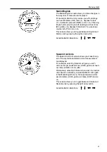
Page 33: ...essing the right arrow button Available Button Selections Speed Dist Units The Speed Dist Units screen allows you make chang es in the way distance related units of measurement are displayed For example selecting Nautical will give you such units as liter per nautical miles L NM gallon per nauti cal miles G NM or knots KN Alternatively selecting Statute will provide non nautical units based on whe...

Page 34: ...r depth and negative numbers will indicate a shallower depth possibly to in dicate depth under the bottom of the hull or keel or to include a safety margin Available Button Selections Setting Depth Alarm Offset Once you ve initiated depth offset settings you will be allowed to enter a new value Pressing the right arrow button in this screen acknowledges that you do indeed wish to use this new valu...

Page 35: ... lever 1 to the neutral position N Press in button 2 move the lever slightly forward and release the button The shift function is now disengaged and the lever affects only engine speed When the lever is moved back to the neutral posi tion it will automatically re engage IMPORTANT Take care not to engage the drive by mistake Adjusting the friction brake The friction brake only affects the engine sp...

Page 36: ...ibed in this chapter Power Trim is operated from the control position using the panels controls and instruments described in this chapter The Operation chapter will provide more information on running with Power Trim WARNING Avoid extreme trimming of the drive as it may have a negative effect on steering ability Trim controls The drive is trimmed using the button on the control lever option By tri...

Page 37: ...r trail ing Power Trim has an automatic stop that cuts the power when its end limit has been reached The stop is reset automatically when activating down trimming WARNING Never run the engine with the drive in lift range Digital trim instrument The display window will show TRIM while the drive an gle is between 6 and 6 Trim range The display window will show BEACH while the drive angle is between ...

Page 38: ... control lever must always be in neutral be fore starting The engine management system ensures that the engine receives the correct amount of fuel even when the engine is cold The idling speed is also governed by engine tempera ture and is somewhat raised after a cold start Before starting Open the fuel tap Open the seawater intake Do the tasks under the Daily before first start heading in the mai...

Page 39: ...ach time the ignition is turned on all bulbs and LEDs are illuminated in sequence on the main control panel Check that all bulbs and LEDs function Start the engine Start using the ignition switch Turn the key to position 2 Release the key and let the key spring back to position 1 as soon as the en gine has started Stop cranking if the engine does not start with in 20 sek All the warning lamps will...

Page 40: ...f you start the en gine the EVC system automatically starts up When EVC starts up you will hear two short beeps to alert you to the fact that the system is functioning Ad ditionally the Alarm Status Indicator gauge lights will light up and turn off in sequential order When the engine is started power is turned off to the gauges in order to limit battery draw during cranking When the start key is r...

Page 41: ...e water Reading the instruments Read all instruments and alarm displays directly after starting and then regularly during your voyage All the reading on the analogue instruments are also available in the Menu system on the LCD display Coolanttemperature optional The temperature gauge should normally indicate be tween 75 100 C 167 212 F in normal operation If the coolant temperature is too high the...

Page 42: ...itch propeller Ask your Volvo Penta dealer for advice Operation Shifting between forward and reverse should be done at idling Shifting at higher engine speeds can be uncom fortable for passengers and cause unnecessary stress on the stern drive or cause the engine to stop Always do a forwards reverse operation as follows 1 Reduce engine speed to idle and let the boat more or less lose way WARNING N...

Page 43: ...ange is used to achieve maximum comfort under normal operation at all speeds from start to maxi mum speed Since every boat has its own unique characteristics and will be effected in different ways by the factors in volved only general advice is given here on how to get the best trimming angle for your boat It can generally be said that when the boat feels well balanced easy to steer and pleasant t...

Page 44: ...t will also be stored in the form of a fault code for as long as the malfunction remains It is possible to read the fault code during a subsequent service Operating with the drive in the Beach range The beach range is used for operation at reduced speed in shallow water or where water depth is uncer tain IMPORTANT Max permitted engine speed rpm when running in the Beach range is 1 500 rpm Check th...

Page 45: ...n authorized Volvo Penta workshop If only the propeller has been damaged it must be replaced Launch the boat and test drive If there are still vibrations it must be inspected by an authorized Volvo Penta workshop IMPORTANT To prevent galvanic corrosion any damage to the paintwork on the drive and propeller must be repaired before launching the boat please referto Layingup Launching Control of para...

Page 46: ...ct the engine and engine compartment for any leaks Boats with drives The drive must be trimmed in to its maximum to protect the trim cylinders untreated surfaces from fouling IMPORTANT If there is a risk that the drive can run aground it must instead be trimmed out to its maximum lift position Switch off the main switches if the boat is not to be used for some time IMPORTANT Never break the circui...

Page 47: ...r level of galvanic corrosion protection due to oxidation on the sacrificial anodes Before launching the boat the sacrificial anodes on the drive and shield must be cleaned with emery paper to remove any oxidation IMPORTANT Do not use a wire brush or other steel tools when cleaning as these may damage the galvanic protection Transporting on a trailer Before pulling boats with or on to a trailer tr...

Page 48: ...the rated voltage of the help start bat tery is the same as the system voltage of the en gine 2 Connect the red jumper cable to the positive pole of the flat battery and then to the positive pole of the help start battery 3 Connect the black jumper cable to the negative pole of the help start battery and then to a place some distance from the flat batteries such as the negative connection on the s...

Page 49: ... Remove washer 2 and tighten the screw 4 Undo cables A and B from the solenoid valves Water in fuel If the lamp and on the Alarm display flash alternatelly and the buzzer sound three short signals this indicates to much water in the pre fuel filter Water in fuel will be displayed on the tachometer LCD gauge WARNING Do not continue operation if there is water in the fuel trap This could cause serio...

Page 50: ... temperature is too low 13 Lubricating oil level too low 14 Blocked oil filter 15 Defective incorrect propeller 16 Defective engine mounting 17 Too little coolant 18 Blocked seawater intake pipe filter 19 Circulation pump drive belt slipping 20 Defective impeller 21 Defective incorrect thermostat 22 Lubricating oil level too high 23 Alternator drive belt slipping Symptom and possible cause Starter...

Page 51: ...the Button Panel to acknowledge the message The alarm buzzer will be come silent The lights will go off when the fault disappear The diagnostic function affects the engine in the following ways when 1 The diagnostic function has discovered a minor malfunction which does not damage the engine Reaction The engine is not affected 2 The diagnostic function has discovered a serious malfunction which wi...

Page 52: ...oll down to the next alarm by using the down arrow button You can leave this warning screen at any time by pressing the left arrow button Once you have left the displayed fault screen you will be returned to the original screen you were viewing before the error occurred EVC System Malfunctions Volvo Penta continually strives to manufacture prod ucts that are foolproof Consequently our products are...

Page 53: ...ine oil Checking the level page 56 Coolant Checking the level page 61 General inspection of drive propeller shield Leakage and function check not shown Every 14 days Battery Checking of the electrolyte level page 67 Seawater filter Cleaning page 63 SX and DP S drives Checking sacrificial anodes page 73 XDP drives Checking sacrificial anodes page 79 SX and DP S drives Checking of oil level page 74 ...

Page 54: ...s Leakage check not shown Outboard drive check for function and wear not shown Bushes shaft stubs in shield and suspension fork Propeller shaft seal Propeller shaft checking straightness Gear change mechanism and control cable Steering Every 1200 hours at least every 5 years Heat exchanger Inspection Cleaning not shown Intercooler Inspection Cleaning not shown Control cables and seals Change not s...

Page 55: ...before starting the engine and after stopping when the engine has been turned off This will help you to quickly detect abnormalities that have occurred or are about to occur Look especially carefully for oil fuel and coolant leaks loose bolts worn or slack drive belts loose connec tions damaged hoses and electric cables This inspec tion takes only a few minutes but can prevent serious operating di...

Page 56: ...orrosion damage the pipe must be repaired or replaced with a new one 1 Undo the clamps and detach the hose 2 Check the contact surface In case of serious corro sion damage the pipe must be repaired or replaced with a new one Air filter Changing 1 Remove the air filter cover 2 Remove the old air filter 3 Clean the air filter cover housing if necessary Take care not to allow impurities to enter the ...

Page 57: ...ng Oil grade Sulphur content in fuel by weight 1 0 1 0 VDS 2 VDS 3 ACEA E5 och API CH4 200 h or 12 month 100 h or 12 month SAE5W 30 30 20 10 0 10 20 30 40 22 4 14 32 50 68 86 104 15o C SAE15W 40 25o C SAE10W 30 10o C SAE20W 30 0o C SAE30 SAE40 10o C o C o F NOTE Mineral based oil either fully or semi synthetic can be used on condition that it complies with the quality requirements above VDS Volvo ...

Page 58: ...mend ed grades of oil please refer to previous page IMPORTANT Do not fill the oil above the MAX level Oil filter Changing The oil filter is pro environmental NOTE Change the oil filter at each oil change WARNING Hot oil and hot surfaces can cause burns 1 Put a suitable vessel underneath the filters to avoid oil spillage 2 Unscrew the lid on the oil filter 3 Wait a few minutes to let the filter dra...

Page 59: ... filter Changing in this chapter 5 Fill up with oil to the correct level through the valve cover cap Please refer to Technical Data for oil volume 6 WARNING Working with or going close to a run ning engine is a safety risk Watch out for rotating components and hot surfaces Start the engine Let the engine run till operation temperature is reached temperature gauge indi cate a value between 75 100 C...

Page 60: ...IMPORTANT Coolant must be used all year round This applies even if there is never any risk for frost to ensure that the engine has an adequate protection against corrosion Future warranty claims on the engine and additional equipment may be rejected if an unsuitable coolant has been used or if the instructions concerning coolant mixing have not been followed NOTE The anti corrosive agents become l...

Page 61: ...increase the risk of overheating and will give reduced freezing protection IMPORTANT Coolant must be mixed with pure water use distilled de ionized water The wa ter must fulfill the requirements specified by Volvo Penta see Water quality IMPORTANT It is extremely important that the correct concentration of coolant is added to the system Mix in a separate clean vessel before adding into the cooling...

Page 62: ... a facility for destruc tion Checking the coolant level WARNING Stop the engine and allow it to cool before opening the filler cap Steam or hot coolant may spurt out Hot oil and hot surfaces can cause burns 1 Turn the filler cap slowly counter clockwise and let any pressure escape from the system before re moving the cap 2 The coolant level should be between the MAX and MIN marking on the expansio...

Page 63: ...which the water is pumped through the intercooler and heat exchanger Finally the water is pumped into the exhaust pipe elbow where it is mixed with the exhaust gases WARNING Always close the seawater cock There is a risk that water will enter while working on the seawa ter system if the boat is in the water Water may flow into the boat if a hose plug or similar object located below the waterline i...

Page 64: ...utlet 2 Take care of filling 3 WARNING Approaching a running engine is dangerous Watch out for rotating components and hot surfaces IMPORTANT The impeller will be damaged if it runs dry Set the gear control lever in the neutral position Check that nobody is near the propellers Start the engine Let it run at fast idle a few min utes Stop the engine 4 For inhibiting fill a bucket with antifreeze mix...

Page 65: ... seawater piping WARNING Risk for water penetration Close the sea cock For the vacuum valve to work satisfactorily it must be taken to pieces twice a season or when leakage occurs Remove the entire valve from the bulkhead where it is installed Undo the lid of the valve remove the gasket and diaphragm and remove any deposits If the diaphragm is distorted put a new one in Installation must always be...

Page 66: ...e fuel soaked rags so that they cannot cause a fire Fuel filter Change 1 Close the fuel valve valves 2 Clean the filter bracket and put a suitable vessel under the filter 4 Unscrew the filter use a filter wrench if needed 5 Clean the sealing surfaces of the filter bracket Make sure the filter is absolutely clean and the sealing surfaces are undamaged Moisten the seal ing rings with engine oil NOTE...

Page 67: ... 5 Start the engine and check for leaks Bleeding the fuel system The fuel system must be bled e g after changing fuel filter if the fuel tank has been run dry and after long stops WARNING Never detach the pressure pipes 1 Position a container under the fuel filter 2 Unscrew the venting screw on top of the filter bracket 1 3 Pump the fuel using the hand pump 2 on the filter bracket until there are ...

Page 68: ...as stopped If the circuit between the alterna tor and the battery is cut off when the engine is running the alternator can be seriously damaged For the same reason charging circuits must never be switched over while the engine is running IMPORTANT Never break the circuit with the main switches while the engine is running Fuses The engine is fitted with two blade fuses 1 20 A lo cated on the right ...

Page 69: ...thout de lay Connectinganddisconnecting First connect the red battery lead to the battery ter minal Then connect the black battery lead to the bat tery terminal When disconnecting the battery disconnect the lead black first and then the lead red Cleaning Keep batteries dry and clean Oxidation or dirt on the battery and battery terminals can cause short circuits voltage drop and discharge especiall...

Page 70: ... battery has discharged it must be charged If the boat has not been used for some time charge the bat tery and then trickle charge it see manufacturer s rec ommendations A poorly charged battery will be dam aged and may burst in cold weather IMPORTANT Follow the instructions supplied with the battery charger carefully To avoid elec trolytic corrosion when an external charger is con nected always d...

Page 71: ...hore power is connected the protector ground should be ashore never in the boat Shore power should always have a ground fault circuit breaker Shore power units transformer rectifier battery chargers etc must be intended for marine usage and the high tension circuit must be galvanical ly separated from the low tension circuit 2 Route and clamp electric cables so that they will not be exposed to rub...

Page 72: ...ed between its terminal and the fuse block and the terminal and the terminal block for the boat s electrical equipment The main switch for the auxiliary battery must cut off all pow er consuming equipment connected to that battery and be turned off when power is no longer needed All equipment connected to the auxiliary battery should have separate switches To simultaneously charge two independent ...

Page 73: ...er for oil grades and volume IMPORTANT Never over fill the revers gear The oil level must always be inside or at the rec ommended levels Oil change and filter change 1 Clean around the cover 2 so that there is no risk of the dirt falling into the filter housing 2 Undo the screws 1 Remove the cover 2 and gasket 3 3 Carefully remove the filter 4 Clean the filter in kerosene leave the gasket 5 in pla...

Page 74: ... lubricated directly after launching Vent the bushing by pressing it together while press ing down on the shaft until water appears Then press in approx 1 cc water repellent grease into the seal IMPORTANT The seal must be checked every 600 hours and changed as necessary The seal must be changed every five years however ...

Page 75: ...he chapter Laying up and launching Sacrificial anodes Checking 1 Check the sacrificial anodes at the front edge of the drive 1 and under the shield 2 every 14 days 2 Replace with new anodes when approximately 30 of the anode has been eroded Note that most stainless steel propellers accessories use the sacrificial anodes faster than normal IMPORTANT Tighten the new anodes so that there is a good me...

Page 76: ...to run out Deposit the used engine oil at a properly designated disposal site 4 Install the plug with a new o ring IMPORTANT If the oil is colored gray then wa ter has entered the drive Please contact your au thorized Volvo Penta dealer 5 Trim the drive up slightly Remove the rear cover 2 and remove the plug 3 and its o ring 6 Measure out the correct amount of oil and fill up through the hole for ...

Page 77: ... quality and capacity Please refer to the Technical Data chapter NOTE If unable to fill the drive unit through oil drain plug B the drive can be filled by trimming it up a few degrees and filling through the oil level plug C 6 When filled to the proper level install oil level dipstick and oil level plug first to prevent excessive oil loss then the oil drain plug Tighten oil level and drain plugs s...

Page 78: ...vel When checking and topping up the oil it is important that no dirt gets into the oil Keep everything very clean 1 Trim the drive to the maximum down position Check that the oil level is between the MAX and MIN markings on the oil container 2 Remove the oil filler cover 1 to fill with oil Use automatic transmission fluid After filling a completely drained reservoir the system should be bled by t...

Page 79: ... injury Please contact your near est authorized Volvo Penta dealer for assistance 1 2 Lubrication CV joint 1 Remove the drive from mounting fork 2 Press in grease until it is forced out of the bearing Use an EP wheel bearing grease NOTE The splined joint on the shaft 1 must be greased using molybdenum grease 3 Lubricate the two O rings 2 with a little engine oil WARNING Removal of the drive requir...

Page 80: ...e units in twin installation In Duo Prop drive unit twin installation the drive unit must be adjusted so operation is free from cavitation To adjust measure the distance A between the cent er line of the two transom shields Adjust tie bar so the distance B between the center of the cavitation plate is equal to distance A Trim fin setting SX drive No adjustment is required if the boat has power ste...

Page 81: ...hich diminishes the galvanized protection Even a new an ode can be oxidized on the surface Therefore always clean the sacrificial anodes before launching the boat IMPORTANT Use emery paper Do not use a wire brush or other steel tools when cleaning as these may damage the galvanic protection Replacing sacrificial anodes 1 Remove the screw holding the anodes onto the gearcase Set the screws aside as...

Page 82: ...to the drain plug If moisture or metal flakes appear in the drive unit oil take the boat to your Volvo Penta dealer If the oil level is low add only enough lubricant to bring the oil level to just below the vent hole Draining the Drive Unit 1 Place the drive unit in the run down position NOTE Special tools are required to remove Duoprop propellers 2 Remove propellers and mounting hardware 3 Remove...

Page 83: ... down position Remove the vent plug and check the oil level Reinstall the vent plug and tighten securely 6 Re install the propellers You may refer to the section entitled Propeller Care for instructions on replacing the propeller 7 Check the oil level oil must appear to the opening to the oil vent hole Add oil if required through the vent hole Please refer to the section entitled Technical Data fo...

Page 84: ... drive bellows secure the drive unit in a raised position in such a way that it cannot fall A falling drive may cause serious injury Check the drive unit bellows for fractures and deterioration Check tightness of all hose clamps Tie Rod Twin Installations Only Check the rod connecting the drive units particularly if you hit an obstacle If the tie rod is bent loose or damaged have it serviced immed...

Page 85: ...possible If the power steering system cannot be correc ted on board proceed at a reduced speed The boat will be steerable but with increased effort See your Volvo Penta dealer as soon as possible to correct your power steering system At slow speeds no wake your boat may tend to wander This is normal and may be overcome by anticipating bow direction and correcting with steering wheel A slightly hig...

Page 86: ...96 108 Nm 8 Install the locking tab washer 2 so the split pin can be inserted in the hole on the shaft Install split pin 1 IMPORTANT Always use a new split pin do not reuse the old one Propellers For best performance and fuel economy the engine speed should be within the maximum RPM range please refer to Operation Cruising speed If the engine speed at maximum RPM falls outside the max RPM range th...

Page 87: ...ater filter if installed Clean and inhibit the seawater system Remove the impeller from the seawater pump Store the impeller in a sealed plastic bag in a cool place Check the condition of the engine coolant anti freeze Top up if required IMPORTANT An anti corrosion mixture in the en gine coolant system provides no protection against freezing If there is any possibility the en gine will be subjecte...

Page 88: ...hull in this chapter Change the sacrificial anode on the drive Install propellers Launch the boat Check for leaks Start the engine Check that there are no fuel en gine coolant or exhaust gas leaks and that all con trol functions are operating Clean the outside of the engine Do not use a high pressure spray to clean the engine Touch up any damaged areas of paintwork with Volvo Penta origi nal paint...

Page 89: ...nt be ap plied onto the original paintwork on the drive without sanding it down first Teflon is the registered trademark of the Du Pont Corp Underwaterhull All types of paints with antifouling properties are poi sonous and cause damage to the marine environment Avoid the use of such agents Most countries have in troduced legislation controlling the use of antifouling agents Always abide by these r...

Page 90: ...e engine Please refer to Maintenance Lubrication to check and top the oil up Check that the oil filter is not blocked Please refer to Maintenance Lubrication system Check that no leakage occurs Contact a Volvo Penta workshop if the fault remains O WATER IN FUEL Explanation Water in water trap in fuel pre filter Reaction No immediate reaction Could cause serious engine damage Action Stop the engine...

Page 91: ...nta workshop if the fault remains O DRIVE TRIM HIGH Explanation Engine to high for current trim angle Reaction Steering becomes unstable Only trim down is possible Action Adjust trim level Contact a Volvo Penta workshop if the fault remains O FUEL LEVEL LOW Explanation Low fuel level Action Check the fuel level Contact a Volvo Penta workshop if the fault remains R O ENGINEELECTRICALFAULT Explanati...

Page 92: ...ectrical system Reaction Depending on fault cause Action Please contact a Volvo Penta workshop if the fault remains O KEY SWITCH FAULT Explanation System fault in EVC MC electrical system Reaction Depending on fault cause Action Please contact a Volvo Penta workshop if the fault remains ...

Page 93: ...een min and max markings 1 5 liter Oil grade VDS2 VDS 3 ACEA E5 eller API CH 4 Viscosity SAE x15W 40 Cooling system Thermostat open fully open 80 C 95 C 176 203 F Freshwater system volume app 12 5 liter 3 3 US gal Volume between min amd max 0 75 liter 0 2 US gal Electrical system System voltage 12V Starter motor battery capacity 1 x 88Ah 800cca Alternator rated power max 14V 140A Starter motor rat...

Page 94: ... 0 6 US gal XDP drive Type designation XDP B Oil grade DuraPlus GL5 synthetic gear lube Oil volume 2 5 liter 2 6 quarts Reverse gear excluding oil cooler Type designation HS25A HS45A Gear ratio 1 92 1 2 43 1 Angle output shaft 8 8 Oil volume approx 1 8 liters 0 48 US gals 2 5 litres 0 7 US gals Oil grade ATF Dexron II III ATF Dexron II III Weight 31 kg 68 lbs Power Trim Oil volume 1 6 liter 0 4 US...

Page 95: ...er als Fax an Document Distribution Center Order Department ARU2 Dept 64620 SE 405 08 Göteborg Schweden Fax 46 31 545 772 Die Bestellung kann auch über das Internet erfolgen http www volvopenta com manual coupon Ja ich will kostenlos eine Betriebsanleitung in deutscher Sprache erhalten Publikationsnummer 7744364 Name Anschrift Land 42200 615001 155099900192 Notez que l offre est valable pendant 12...

Page 96: ...ación y posteriormente solamente mientras duren las existencias Franquear o enviar fax a Document Distribution Center Order Department ARU2 Dept 64620 SE 405 08 Göteborg Suecia Fax 46 31 545 772 El pedido puede hacerse tam bién por internet http www volvopenta com manual coupon Sí gracias deseo recibir gratuitamente un libro de instrucciones en español Número de publicación 7744366 Nombre Direcció...

Page 97: ...ller fax til Document Distribution Center Order Department ARU2 Dept 64620 SE 405 08 Göteborg Sverige Fax 46 31 545 772 Bestillingen kan også ske på internet http www volvopenta com manual coupon Ja tak jeg vil gerne gratis have en instruktionsbog på dansk Publikationsnummer 7744368 Navn Adresse Land 42200 615001 155099900192 Huomaa että tarjous on voimassa 12 kuukautta veneen toimituspäivä määräs...

Page 98: ...7744372 Nome Endereço País 42200 615001 155099900192 ÐÑÏÓÏ Ç ÁõôÞ ç ðñïóöïñÜ éó ýåé ãéá ñïíéêÞ ðåñßïäï 12 ìçíþí áðü ôçí ðáñÜäïóç ôïõ óêÜöïõò ÌåôÜ ôï ðÝñáò ôçò åí ëüãù ñïíéêÞò ðåñéüäïõ ç äéáèåóéìüôçôá ôùí áíôéôýðùí èá åîáñôÜôáé áðü ôçí ðïóüôçôá ôùí áðïèåìÜôùí Ôá õäñïìÞóôå áõôü ôï êïõðüíé óôçí ðáñáêÜôù äéåýèõíóç Þ óôåßëôå ôï ìå öáî óôïí ðáñáêÜôù áñéèìü öáî Document Distribution Center Order Departme...

Page 99: ......

Page 100: ...7744362 English 12 2004 ...

Reviews: