background image

87

60

Install the air pipe compressor – air cleaner. Use new
O-rings and dip them in soap solution to facilitate in-
stalling the air pipe . Install air cleaner. Wrench 10,
11 mm. Install the pipe between the turbo – the air
cleaner – the compressor. The compressor terminals,
both intake and output sides are sealed with a silicon
sealing agent, such as Permatex ® No. 6 or Loctite ®
Silicon sealing.

61

Install the electrical box and connect all components.
Wrench 8, 10, 12, 13 mm.

Repair Instructions

Drive belts, tensioning, 31/41 series

62

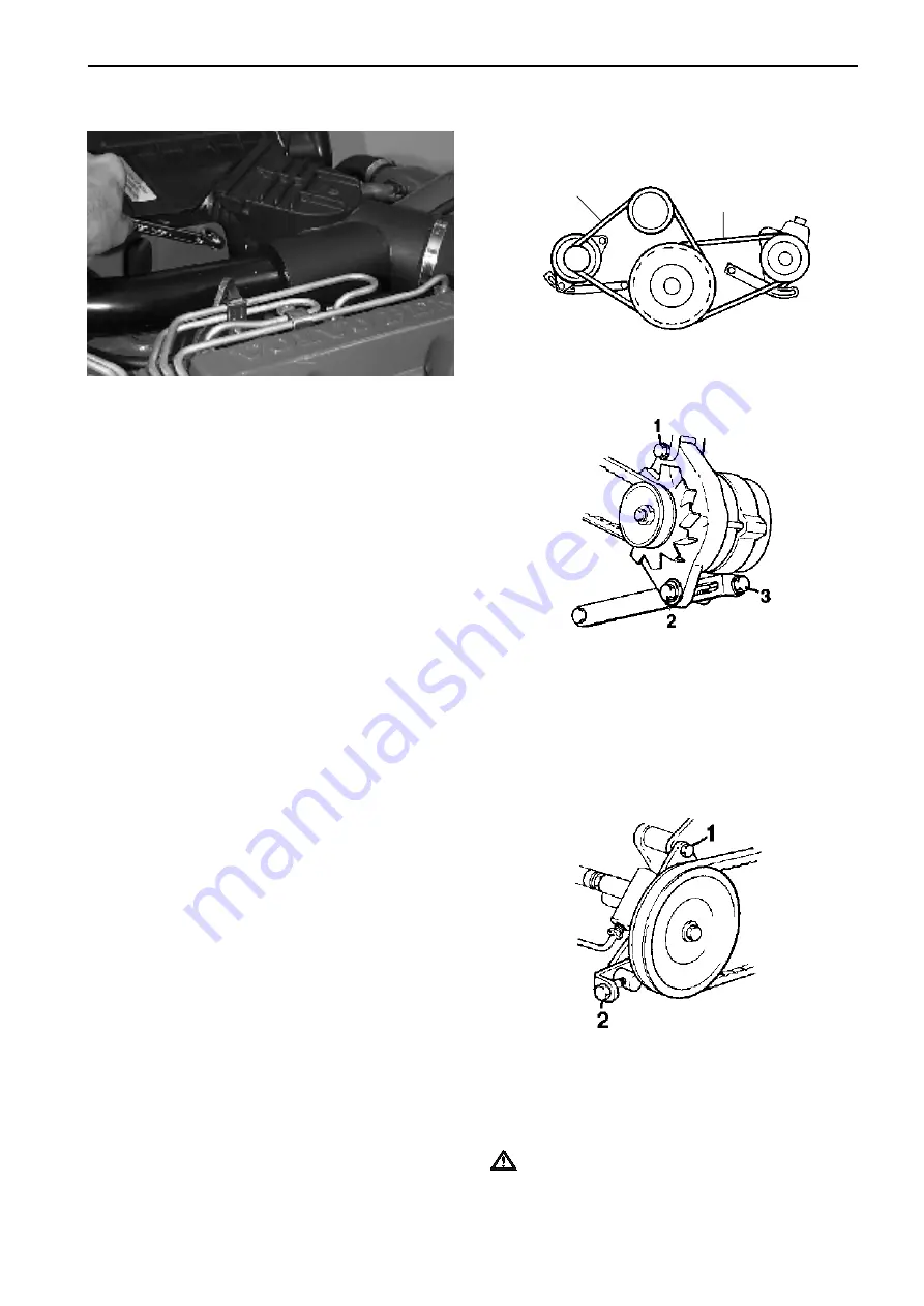
Alternator belt

Undo alternator fixing screws (1) and (2). Tension the
belt with adjustment screw (4), so that the belt can be
pressed down about 10 mm between the pulleys at
(A). Tighten screws (1) and (2).

63

Servo pump belt

Undo retaining screw (1). Tension the belt with adjust-
ment screw (2), so that the belt can be pressed down
about 10 mm under normal thumb pressure between
the pulleys at (B). Tighten screw (1).

IMPORTANT! Re-check belt tension on all belts
after the engine has warmed up. Do this check
while the belts are still warm.

A

B

Drive belts, inspection points

Summary of Contents for 300 Series

Page 1: ...Engine Body Workshop Manual 2 0 B 31 32 41 42 43 44 300 series ...

Page 2: ......

Page 3: ... Engine Body Marine Engines MD31A TMD31B D L A TAMD31B D S O L A S L A M A P A S A AD31B D L A P A KAD32P TMD41B D L A TAMD41B D S O L A S L A M A P A H A H B D41B D L A AD41B D L A P A TAMD42AWJ BWJ WJ KAMD42A B P KAD42A B P KAMD43P KAD43P KAMD44P A P B P C KAD44P A P B P C KAMD300 A KAD300 A Contents Safety information 2 General information 5 Special tools 9 Other special equipment 12 Design and...

Page 4: ...and starter elements etc and liquids in supply lines and hoses when the en gine is running or has been turned off immedi ately prior to starting work on it Reinstall all protective parts removed during service opera tions before starting the engine Check that the warning or information decals on the product are always clearly visible Replace decals that have been damaged or painted over Never star...

Page 5: ...ed at an approved site for de struction together with used lubricating oil con taminated fuel paint remnants solvent de greasing agents and waste from washing parts Never allow a naked flame or electric sparks near the batteries Never smoke in proximity to the batteries The batteries give off hydrogen gas during charging which when mixed with air can form an explosive gas oxyhydrogen This gas is e...

Page 6: ... with adjacent explosive media Safety Precautions Fuel delivery pipes must not be bent or straight ened under any circumstances Damaged pipes must be replaced Remember the following when washing with a high pressure washer Never aim the water jet at seals rubber hoses or electrical components Never use a high pressure washer for engine cleaning Always use fuels recommended by Volvo Pen ta Refer to...

Page 7: ... of Service Bulletins Replacement parts Replacement parts for electrical and fuel systems are subject to statutory requirements US Coast Guard Safety Regulations for example Volvo Penta Genu ine parts meet these requirements Any type of dam age which results from the use of non original Volvo Penta replacement parts for the product will not be covered under any warranty provided by Volvo Penta Cer...

Page 8: ... malfunction or a shorter operational life Our joint responsibility Each engine consists of many connected systems and components If a component deviates from its technical specification the environmental impact of an otherwise good engine may be increased significant ly It is therefore vital that wear tolerances are main tained that systems that can be adjusted are adjust ed properly and that Vol...

Page 9: ...ls and gap siz es in the engines To ensure service work is correctly carried out it is important that the correct sealant and locking fluid type is used on the joint where the agents are re quired In this Volvo Penta Service Manual the user will find that each section where these agents are applied in production states which type was used on the engine During service operations use the same agent ...

Page 10: ...d in a fire The seals must never be burned off when disassembling or be burnt afterwards in any thing other than a special disposal site Always used chloroprene rubber gloves gloves for handling chemicals and protective glasses Treat removed seals in the same way as corro sive acid All remains even the ash can be ex tremely corrosive Never use compressed air jets for blowing clean Put old seal rem...

Page 11: ...nsert 884 888 9 Plate liner puller 884 895 4 Lock pin for flywheel pump setting 884 931 7 Puller for injector sleeve 31 32 41 42 43 884 945 7 Drift for installing injector sleeve 31 32 41 42 43 884 992 9 Reamer valve guide 31 32 41 42 43 885 128 9 Valve spring tensioner 885 131 3 Puller for dismantling injector nozzle 31 32 41 42 43 Special tools In all cases where it is practical the tool number ...

Page 12: ...tor 44 300 885 274 1 Sealing plate for test pressurization of cylinder head 885 289 9 Brush for cleaning bottom of copper sleeve and for sealing sleeve between copper sleeve and cylinder head 885 301 2 Tool for pressing in the Alfa reset piston 44P A 357 8670 6 Puller for compressor magnetic clutch 32 42 43 44 300 999 1867 4 Drift for removing and installing rocker arm bushing 999 2000 1 Standard ...

Page 13: ... 999 6272 2 Press tool for cylinder liner when measuring liner height 2 x 999 6385 2 Drift for replacing rear crankshaft seal 999 6404 1 Press tool for the crankshaft and poly gon hub 999 6532 9 Terminal plate for test pressurization of cylinder head 999 6598 0 Plate for installing cylinder liner 999 6858 8 Drift for removing circulation pump pulley 999 6860 4 Puller for oil pump drive 999 6936 2 ...

Page 14: ...re 951 0060 8 Multimeter 999 6591 5 Nipple oil pressure gauge 999 6662 4 Test pressurization equipment 999 6666 5 Nipple checking boost pressure 999 9179 6 Wrench for removing fuel oil filters 999 9683 7 Rocker indicator 999 9696 9 Magnetic stand for dial indicator 998 6485 2 Unit stand 999 9946 8 Engine fixture for unit stand 1 Diagram of the special tool for the Turbo The tool is not supplied by...

Page 15: ...a heat exchanger The turbocharger supplies the engine with pressurized fresh air which gives greater air capacity This means that the amount of fuel injected can be increased which gives better engine power The engines are equipped with seawater cooled charge air cooler CAC which lower the intake air temperature after turbo compression This lowers the volume of the air and more air can be supplied...

Page 16: ...rive serial number 6 Reverse gear drive product number 7 Volvo Penta Part Number P N 8 Pump type and version 9 BOSCH P N 10 Engine designation and product number 11 Engine Product number 12 Serial number Base engine number 13 Certification number 14 Certification sign 15 Control unit only EDC engines 16 IMO decal only engines above 130 kW 174 bhp Design and Function ...

Page 17: ...5 Thermostat housing 6 Oil cooler 7 Lubricating oil filter 8 Generator 9 Seawater filter 10 Terminal box with semi automatic fuses 11 Oil filler cap 12 Dip stick 13 Charge air cooler CAC 14 Seawater pump 15 Steering servo pump 16 Injection pump 17 Fuel pump 18 Fuel filter 19 Oil cooler power steering 20 Starter motor AD31L P SX ...

Page 18: ...ap 3 Dip stick 4 Charge air cooler CAC 5 Air Cleaner ACL 6 Injection pump 7 Seawater filter 8 Fuel filter 9 Fuel pump 10 Starter motor 11 Turbocharger 12 Expansion tank 13 Thermostathousing 14 Oil cooler 15 Lubrication oil filter 16 Alternator 17 Heatexchanger TAMD31S HS25A 14 15 16 17 13 12 11 ...

Page 19: ...es 3 Dip stick 4 Charge air cooler CAC 5 Seawater filter 6 Seawater pump 7 Injection pump 8 Generator GEN 9 Fuel filter 10 Fuel pump 11 Starter motor 12 Turbocharger 13 Air Cleaner ACL 14 Compressor 15 Oil cooler 16 Silencer compressor 17 Heat exchanger 18 Steering servo pump 19 Oil filter ...

Page 20: ...p 3 Charge air cooler CAC 4 Air Cleaner ACL 5 Seawater filter 6 Seawater pump 7 Injection pump 8 Fuel filter 9 Fuel pump 10 Starter motor 11 Turbocharger 12 Air Cleaner ACL 13 Expansion tank 14 Thermostat housing 15 Heat exchanger 16 Oil filter 17 Oil cooler 18 Generator AD41P DP ...

Page 21: ...er cap 3 Charge air cooler CAC 4 Air Cleaner ACL 5 Engine coolant temperature ECT 6 Seawater pump 7 Injection pump 8 Fuel filter 9 Fuel pump 10 Starter motor 11 Turbocharger 12 Air Cleaner ACL 13 Expansion tank 14 Heat exchanger 15 Thermostat housing 16 Oil filter 17 Oil cooler 18 Generator ...

Page 22: ...Oil filter 4 Charge air cooler CAC 5 Seawater filter 6 Seawater pump 7 Injection pump 8 Generator 9 Fuel pump 10 Fuel pump 11 Starter motor 12 Turbocharger 13 Air Cleaner ACL 14 Expansion tank 15 Compressor 16 Heat exchanger 17 Oil cooler 18 Silencer compressor 19 Steering servo pump KAD43P DPX ...

Page 23: ...leaner ACL 13 Expansion tank 14 Compressor 15 Heat exchanger 16 Oil cooler 17 Silencer compressor Design and Function 1 Terminal box with semi automatic fuses 2 Oil filler cap 3 Charge air cooler CAC 4 Seawater pump 5 Injection pump 6 Generator 7 Fuel filter 8 Fuel pump ...

Page 24: ...omatic fuses 2 Oil filler cap 3 Charge air cooler CAC 4 Injection pump 5 Seawater pump 6 Fuel filter 7 Fuel pump 8 Starter motor 9 Turbocharger 10 Air Cleaner ACL 11 Expansion tank 12 Heat exchanger 13 Thermostat housing 14 Oil filter 15 Oil cooler 16 Generator ...

Page 25: ...filter 5 Charge air cooler CAC 6 Seawater filter 7 Seawater pump 8 Generator 9 Fine fuel filter 10 Fuel pump KAD44P DPX 11 Oil cooler power steering 12 Starter motor 13 Turbocharger 14 Air Cleaner ACL 15 Expansion tank 16 Compressor 17 Oil cooler 18 Silencer compressor 19 Heat exchanger 20 Steering servo pump ...

Page 26: ... 4 Oil filter 5 Charge air cooler CAC 6 Seawater pump 7 Generator 8 Fuel filter 9 Feed pump fuel 10 Dipstick reverse gear 11 Type plate 12 Water cooled exhaust elbow 13 Air Cleaner ACL 14 Oil dipstick 15 Topping up the engine coolant 16 Compressor 17 Oil filter reverse gear 9 10 8 6 2 3 4 5 1 7 11 12 13 14 15 16 17 ...

Page 27: ...filter engine 6 Intercooler 7 Startermotor 8 Fuel supply pump 9 Fuel filter 10 Injection pump 11 Alternator 12 Sea water pump 13 Turbocharger 14 Air filter 15 Dipstick engine 16 Coolantfiller 17 Expansion tank 18 Supercharger 19 Servo pump steering 20 Heatexchanger 21 Trim cylinder 22 Coolingwaterinlet 23 Oil filler drive 24 Dipstick drive Design and Function ...

Page 28: ...stons are made of an aluminum alloy The up per compression ring which leads off the greater part of the heat transferred by the piston rings is located in a forged piston ring carrier of high alloy cast iron This gives the piston ring groove long service life despite the heat stresses The piston ring grooves for other piston rings are machined di rectly into the piston All engines have piston cool...

Page 29: ...artly through an expander spring on the inside of the ring The opening of the expander ring should be placed on the opposite side of the gap in the oil ring A B C Cylinder liners The cylinder liners are of the wet type and are re placeable They are made of a special alloy cast iron and are spun cast Four rubber O rings are used as the cylinder liners outer seals The three lower rings 1 2 are locat...

Page 30: ...size and aligned after pressing in Transmission The transmission consists of gear wheels with helical teeth Transmission 1 Crankshaft gear 2 Intermediate gear for oil pump 3 Intermediate gear for oil pump 4 Intermediate gear for camshaft 5 Camshaft gear 6 Injector pump and water pump gear Crankshaft The crankshaft is supported on seven main bearings The thrust bearing consists of thrust washers lo...

Page 31: ...a trapezoidal gudgeon pin end Early and late model con rods can be mixed however The gudgeon pin bushings are steel with bronze alloy coatings Flywheel The flywheel is screwed to a flange at the rear end of the crankshaft It is statically balanced and fully ma chined The starter ring gear is pressed onto the fly wheel Vibration damper The vibration damper consists of a hermetically sealed housing ...

Page 32: ...oints with gaskets and rubber hoses and electrical components 13 Drain out engine oil 14 Dismantle reverse gear if necessary General If possible a condition test should be carried out be fore every major service correction so that the engi nes condition can be established and any contributory fault causes discovered A condition test requires the engine to be run so this should be carried out befor...

Page 33: ...er and size of screws is followed so that a se cure attachment of the engine is obtained Necessary screws 41 42 43 44 300 series 2 screws M12x30 mm 2 screws M16x30 mm The following components must be removed from the engine before the fixture can be attached and the en gine installed on the stand Compressor 42 43 44 300 series heat exchanger with expansion tank oil cooler with oil distribution hou...

Page 34: ...g temperature and shut it off Dismantle all injectors and test cylinders in turn and order IMPORTANT Cleanliness is extremely impor tant no dirt must get into the fuel system Plug terminals on disconnected injectors and fuel lines Compression should be read off at normal starter motor speed A deviation of up to 10 below the fig ure given in the Workshop manual Technical data is acceptable Low comp...

Page 35: ...42 43 44 300 Other engines Remove the oil filter with 999 9179 4 Remove the compressor bracket and remove the compressor Wrench sizes 14 mm and 15 mm KA M D32 42 43 44 300 IMPORTANT Cover the compressor intake and outlet pipes with clean paper or similar so that nothing can fall into the compressor housing 5 Disconnect the coolant hoses from the heat ex changer housing charge air cooler CAC oil co...

Page 36: ...ixture partly to al low the oilways to be flushed 10 Lift the engine with the appropriate lifting gear Re move the engine pads Wrench 17 mm Install engine fixture 999 9946 NOTE If the dipstick pipe cannot be removed the fix ture must be modified so that the dipstick pipe is not crimped Install engine in the unit stand 998 6485 11 Remove connectors for oil pressure sensor and oil pressure switch Re...

Page 37: ...ith the fuel system Be alert for fuel spillage diesel oil is hazardous if in frequent contact with the skin 14 Remove fuel filter complete with electronic diesel control EDC unit KA M D44 300 and bracket Wrench 14 mm Remove fuel pipe bracket Wrench 13 mm 15 Remove the delivery line terminals at the fuel pump and injector Wrench 17 mm Lift off the delivery line Remove fuel return line Wrench 10 mm ...

Page 38: ...motor solenoid electrical ter minals Wrench 8 mm and 13 mm 17 Remove electronics box Disconnect all connectors and remove engine wiring in one piece 18 Remove water filter bracket Remove the sea water pump and lift off the filter and pump as one unit Wrench 12 mm 19 Remove the generator Wrench 11 16 5 8 12 mm and 13 mm ...

Page 39: ...the charge air cooler CAC Disconnect the turbocharger TC connector pipe wrench 10 mm Slacken off the support bracket at the bottom edge and on the inside of the CAC and the terminal to the intake manifold Wrench 13 mm and 17 mm 21 Remove the starter motor Wrench 15 mm Remove the injector pump Socket 13 mm Remove supply pump Socket 12 mm Repair Instructions ...

Page 40: ...ove the lifting bracket Socket 13 mm 25 Remove the outer pulley on the circulation pump Socket 12 mm 26 Slacken and remove the circulation pump drivebelt Remove tension reel Wrench 8 mm allen Repair Instructions ...

Page 41: ...cable to the injector on cylinder 1 Separate the connector Remove the screws for the valve cover Carefully press the rubber grommet in using a screwdriver at the same time lifting the valve cover slightly Insert the cable through the hole Remove the valve cover Remove the seal against the valve cover the O rings washer and spring on each injector NOTE The springs on cylinder 1 cannot be removed be...

Page 42: ...are to be re used Lift out the push rods and valve yokes KA M D44 300 and place them in the marked up stand Repair Instructions 4 Remove the injectors Use extractor 885 131 31 32 41 42 43 series and 885 263 44 300 series This is to ensure that the copper sleeves are not extracted as well 5 Remove the cylinder head Socket 14 mm Slacken off the screws in reverse tightening order Remove the inspectio...

Page 43: ... gear wheel in position The gear wheel can otherwise engage incorrectly and be damaged or cause damage 7 Remove oil feed pipe and oil delivery pipe and their bracket Socket 12 mm NOTE The bracket screws have sprung washers which may not be mixed with the other washers 8 Remove the cylinder block reinforcement panel Socket 14 mm NOTE Do not drop the spacer washers between the panel and the engine b...

Page 44: ... the center screw 12 Remove the timing cover socket 12 mm Lift off the fuel injection gear wheel 13 Remove the oil pump Socket 12 mm 14 Remove the intermediate gear Socket 12 mm 15 Remove the camshaft pulley center screw and washer Screw the center screw back in loosely and pull off the camshaft pulley with puller 999 2679 Repair Instructions ...

Page 45: ...draw the camshaft Socket 12 mm 18 Remove the flywheel Use tool 884 895 as a counter hold Socket 19 mm NOTE To minimize the risk of damage to the RPM sensor 44 300 series it should be removed before the flywheel is removed 19 Remove the inner flywheel cover Socket 14 mm 20 Remove the connecting rod cap and press out the pistons Take care not to damage the piston cooling nozzles Socket 17 mm Repair ...

Page 46: ...t 10 mm Removing cylinder liner The cylinder liners should not be removed until it is decided after measurement or some other method that it is absolutely necessary that they are changed See Cylinder liners inspection and measurement 22 Remove the cylinder liners using tools 884 231 884 551 and 884 888 The extractor consists of yoke from 884 551 and center screw and puller nut from 884 231 The ext...

Page 47: ...e cylinder head mating surface Reassembling 3 Install the plugs if they have been removed Clean the plug seats Apply Permatex No 3 or Volvo Penta 1161099 5 sealing compound Insert plugs using a drift or socket 4 Lubricate the valve stems and install the valve in its guide NOTE Follow the markings so that the valves are re turned to the original positions 5 Applies to 44 300 series Install protecti...

Page 48: ...in Be very careful to center the center punch mark 2 Drill with a 3 2 mm 0 125984 hole 1 Drilling depth about 10 mm 0 3937 or when the case hardened layer of the guide pin is reached Use a pillar drill Thread the hole with an M4 tap 2 3 Screw in a stud M4 slide a spacer sleeve over plus a suitably sized washer Pull the guide pin up by scre wing the nut down 4 Inspect and clean the hole for the gui...

Page 49: ...efore use Always follow the safety precautions 1 Connect the pressure test equipment to the pres surized air network and set the pressure gauge to 100 kPa 1 kp cm2 with the relief valve NOTE The relief valve knob can be locked with an axially moved lock ring 2 Then close the shut off valve To ensure that the pressure test equipment is reliable the pressure read ing on the pressure gauge must not s...

Page 50: ...begins at the copper injector sleeve and goes towards the valve seat position The cause of the crack may be that the injector mounting nuts are too tight incorrectly torqued Cracks of this type have never been the cause of gas or fluid leakage because the crack has not continued through to the bottom of the cylinder head When leakage is observed it has been because of pollutants or damage to the c...

Page 51: ... Workshop manual technical data Valve guides replacing Special tools 31 32 41 42 43 series 884 992 999 5218 999 5028 44 300 series 885 238 885 261 1 Press out the valve guide with drifts 999 5218 31 32 41 42 43 series and 885 261 44 300 series 2 31 32 41 42 43 series Lubricate the new guides and press them in with drift 999 5028 The drift gives the guides the correct height A 18 mm above the cylin...

Page 52: ...down just under the edge of the valve seat MIG or MAG weld cover the surrounding area so that any welding drops do not fasten anywhere IMPORTANT Be careful so that the cylinder head is not damaged Repair Instructions 3 Clean the seat position and check that there are no cracks Measure the diameter of the valve seat position De cide using the measurement whether a standard or oversized seat is need...

Page 53: ...rinding the valve guides should be checked and replaced if the wear parameters are exceeded When grinding the valve seat only remove the min imum amount necessary to ensure that the valve seat has the right shape and surface form Valve and valve seat Mill or grind the valve seats A new seat must be ground so that the distance between the cylinder head level and the valve crown surface A measured w...

Page 54: ... should not be unevenly worn or concave Slight wear can be adjusted with a grinder Ovally worn rocker mechanism are replaced 4 Press out the rocker arm bushing with drift 999 1867 Repair Instructions 5 Turn the drift and press the new bushing into place NOTE Ensure that the bushing oil hole is opposite the oilway in the rocker 6 Ream the bushing to an exact alignment on the shaft 22 020 22 041 mm ...

Page 55: ...ions Applies to 31 32 41 42 43 series 1 Pull out the steel ring above the copper sleeve by ex panding tool 884 931 just under the ring NOTE To prevent the extractor stem from damage when extracting the crank must be held and the tight ening carried out with a nut The nut should do the work Applies to all engines 2 Press out the copper sleeve with drifts 884 931 31 32 41 42 43 series and 885 260 44...

Page 56: ...h a nylon brush See Cleaning copper sleeve seat on this page Remove upper seal ring Clean upper and lower guides in the cylinder head Cleaning seat for copper sleeve Special tools 885 289 It is very important that all forms of deposits on the copper sleeve mating surface in the cylinder head are removed before installing the new copper sleeve 1 Mount brush 885 289 on a variable speed drill Maxi mu...

Page 57: ...maged by the tool during installation 5 Hold the tool stem and screw the large nut down The drift clamp is then pressed up through the lower part of the copper sleeve Screw down the nut until the tool stem releases from the sleeve Then pull up the stem and the remove the rest of the tool from the cylinder head Applies to 44 300 series 3 Remove the drift clamp 1 from tool 885 237 Slacken off the to...

Page 58: ...he cylinder head is painted the contact areas of the cylinder head screws must be free of paint Otherwise the pressure in the screwed joint will otherwise be very bad 4 Apply the cylinder head gasket and install the cy linder head 5 Tighten the cylinder head screws in numerical order according to the tightening diagram below in five stages 1st tightening 30 Nm 2nd tightening 60 Nm 3rd tightening 1...

Page 59: ...a tion and check the play on cylinder 5 The valves on cylinder 2 then rock Check the play for the other cylinders in firing order Applies to 44 300 series Slacken off the locknut and the adjuster screw on valve pair no 1 in Cylinder 1 so that there is play be tween the yoke and the valve stem Repair Instructions Valves adjusting NOTE The clearance must never be checked with the engine running the ...

Page 60: ...he other cylinders in firing order Applies to all engines 8 Clean the valve cover replace the damaged gasket Tightening torques see Workshop manual Technical data Test run the engine and check that there is no oil leakage Repair Instructions 3 Press the valve yoke down 4 Turn the adjustment screw carefully using fingers un til just comes into contact with the valve stem 5 Lock the adjustment screw...

Page 61: ...es along its travel At each measurement point measurements should be done along and across the length of the engine Repair Instructions Cylinder block reconditioning Cylinder block inspection Clean the cylinder block thoroughly and check bear ing position connecting rods and cap for damage Check that all the channels are free of deposits and that the block does not have any cracks Smaller crack bu...

Page 62: ...llus tration the angles of which are calculated to give op timal lifetime When honing in conjunction with piston ring replacement the original pattern must be followed to retain the lubricating function The honing lines must be regularly formed and evenly cut in both directions over the whole surface NOTE The correct speed must be held on the honing tool in order to obtain the correct pattern 1 Cl...

Page 63: ...gh the bushing under its own weight at room temperature NOTE The cylinder liner wear should be checked before replacing piston rings and connecting rod bushings See Cylinder liner inspection and mea surement There are two types of con rods Late model con rods have a trapezoidal gudgeon pin end Both types can be mixed during engine renovation however Before the gudgeon pin bush is changed check the...

Page 64: ...ing with engine oil Repair Instructions 3 Position the piston and connecting rod so that the front marking on the pistons arrowed and the num bering on the connecting rods is in the position illus trated 4 Carefully push in the piston bolt with a suitable drift and install the other snap ring NOTE The piston bolt should be pushed in easily not hammered in ...

Page 65: ... they were in before removal Check the piston ring gap on new rings as well For measurement details see Workshop manual Techni cal data for engine variant Note New cylinder liners are supplied complete with pistons and piston rings Piston rings installing C B A Install the piston rings on the piston using piston ring pliers The oil ring C is installed first and can be freely turned The opening in ...

Page 66: ...tting dam age can occur for different reasons The damage oc curs by small metal particles being loosened from the hardened surface Valve lifters and camshafts with minor pitting can be reinstalled It has been found that the damage seldom gets worse Check the camshaft bearing caps and cam lobes for wear Cams can be unevenly worn axially This can be adjusted in minor cases by grinding the cams Repla...

Page 67: ...efully to determine whether it needs reconditioning as follows 1 Measure wear and ovalness with a micrometer Greatest permitted ovalness in Main and big end bearings 0 08 mm maximum conicity 0 05 mm Grind the crankshaft to a suitable undersize if these values are exceeded 2 Judge any surface damage 3 Measure crankshaft lengthwise runout Place the crankshaft on a pair of v shaped blocks under main ...

Page 68: ...uipment manufacturer s instructions for opera tional procedure The shaft must be demagnetized af ter this sort of test Cracks of the following type and locations mean that the crankshaft must be discarded A Lengthwise cracks in the bearing journals and hole edges B Lateral cracking in the marked area C Cracks longer than 5 mm connected to oilway holes Cracks shorter than 5 mm are removed with grin...

Page 69: ...isc Ø 36 42 914 1067 mm the disc can be used down to approximately Ø 720 mm Peripheral speed Grinding wheel 28 33 m s Crankshaft max 0 25 m s Cooling 3 oil emulsion Soluble It is important that the cooling is powerful ideally with flushing from above and below The disc should be sharpened with a grinding diamond Peripheral dimension 0 1 mm revolution Side measurement 0 2 mm revolution Cutting dept...

Page 70: ...s or other damage Check that the gear collar is not damaged or worn Replace gear collar or flywheel as necessary 2 Clean the crankshaft flange contact area against fly wheel 3 Clean flywheel contact area against crankshaft flange 4 Check that the flywheel locating pin in the crankshaft is in place and undamaged 5 Lift the flywheel into place and install screws 6 Tighten the flywheel screws to 65 N...

Page 71: ...ons Gear collar replacing flywheel dismounted 1 Drill 1 2 holes in a notch on the gear collar Split the gear collar at the drilling point with a chisel and re move the gear ring 2 Brush the flywheel contact area with a steel brush 3 Heat the new gear collar in an oven or with a welding torch to maximum 180 200 C WARNING If use a welding torch great care must be taken to ensure that the gear collar...

Page 72: ...gauge magnetic mounting on the fly wheel and set the dial indicator point on the outer edge of the flywheel housing see illustration Read off the value and the move the dial indicator and mounting to the opposite side of the flywheel The difference in value between these two indications must not exceed 0 15 mm 2 Position the dial gauge magnetic mounting on the fly wheel and set the dial indicator ...

Page 73: ...snap ring 6 from the shaft Press off roller bearing with drift 884 596 Reassembling 4 Press on the new bearing using drift 884 596 Install snap ring 5 Press the shaft into the housing with drift 884 596 Ensure that the snap ring 6 locates correctly in the tool notch Fix the shaft with snap ring 3 6 Press in the bushing 2 with drift 884 596 Fill cavity A with grease P N 1141 644 and press in the se...

Page 74: ...er Check that the sup port surface is not damaged when resetting the dial indicator The check is made with dial indicator 998 9876 and holder 999 2479 The height should be 0 06 0 11 but the difference between two close lin ers must not exceed 0 02 mm Mark the liners so that they have the same position when installed 2 1 Purple 2 Black 3 Black Repair Instructions Lift up the cylinder liner and inst...

Page 75: ... and big ends Turn the piston rings so that the gaps are at approximately 120 to each other In stall the pistons so that the front markings face for ward Use installation ring 999 5031 Repair Instructions 7 Install the big end bearing caps so that the marking matches the marking on the crankshaft Oil the threads Tightening torques see Workshop manual Technical data Socket 17 mm Oil pump installing...

Page 76: ...intake pipe and fix it and the dipstick pipe with hose clamps Only engines intended for V reversing gear 10 Install a new seal ring in the inner bell housing using mandrel 999 6385 NOTE Wipe grease VP part no 1161447 on the inner edge of the seal ring lip and on the crankshaft flange before installing the flywheel Install the flywheel NOTE Fit the two slightly longer screws underneath with the eng...

Page 77: ...the gears mesh with the oil pump intermediate drive gear Repair Instructions 15 Install the camshaft intermediate drive gear as marked on the gear Tightening torque 24 Nm 16 Install the camshaft key Check the camshaft posi tion so that the markings match with the pulley in stalled Heat the camshaft pulley to approximately 100 C and install it on the shaft Tightening torque 85 Nm 12 Install the inn...

Page 78: ...ighten the center screw until the hub has cooled Tightening torque 180 Nm Socket 24 mm 20 Install the oil pan together with a new gasket Cut off any excess edges from the timing cover and flywheel housing gaskets The oil pan gasket joint should be sealed with Permatex No 77 or corresponding silicon agent Tightening torque 15 Nm Socket 12 mm Insert the fuel injection pump pulley as marked on the ge...

Page 79: ...series Install the fuel injection pump Do not tighten the nuts in this position NOTE If the stud bolts have been removed apply Loctite 572 to their threads before reinstalling This reduces the risk of oil leaks IMPORTANT Do not turn the engine with the fuel injection pump drive gear loose This may damage the cogs or engine speed RPM sen sor 32 42 43 series 24 Turn the pump shaft so that the holes ...

Page 80: ... torque 28 Nm Socket 12 mm 26 Install feed pump Socket 12 mm Install starter mo tor Socket 15 mm 27 A B B only upper edge Sealing compound intake manifold C Sealing compound cylinder head Tighten the intake manifold Tightening torque 20 Nm Install circulation pump and belt tensioner bracket Wrench 12 mm 13 mm Install and tension the drive belts NOTE There are several versions of belt tensioners Pl...

Page 81: ...Technical data Socket 14 mm wrench 17 mm Then adjust valve clearance See Valves adjusting 31 Install the nozzles Do not forget the lower O ring on the nozzles 44 300 series only NOTE Ensure that the plane of the return line is as straight as possible NOTE If the copper injector sleeves were not re placed they should be cleaned with brush 885 289 be fore the nozzles are installed Tightening torque ...

Page 82: ...orre sponds to the split pin and the injectors cable termi nal only cylinder 1 44 300 series Inspect the valve cover gasket If it is undamaged and securely fixed to the cover the gasket does not need to be changed If it needs to be replaced carry out the following Carefully clean the gasket seat Apply a thin layer of silicone sealant part no 116 1231 4 to the valve hou sing Put the new gasket on a...

Page 83: ...Connect the cable to the engine cable harness Check that the cable is clear of the rocker arms through the oil filler hole 34 Install the pipe for the smoke limiter 31 32 41 42 43 series only Socket 13 mm 35 Install the lifting brackets Install the thermostat housing using new sealing ring Socket 12 mm 13 mm Install the circulation pump outer pulley 36 Install the exhaust manifold with air filter ...

Page 84: ...8 Remove the center screw on the rear face of the fuel injection pump and install the dial indicator 884 954 with holders 885 139 41 42 43 44 300 series and 885 199 31 32 series Ensure that the indicator is pushed in 3 4 mm Applies only to KA M D44P A 39 Remove the pump s reset cover Use Torx 30 tool 40 Screw out the center screw on tool 885 301 oil the reset piston and install the tool on the pum...

Page 85: ...is too low injection too late and coun ter clockwise if the value is too high injection too early Tighten the pump and dismantle specialtools Rein stall the reset cover 144P A series only NOTE The support bracket at the rear of the pump must block the cylinder block and pump before final tightening so that no tensions are introduced NOTE Do not forget to remove tool 884 895 from the flywheel housi...

Page 86: ... 44 300 Install the hoses from the oil filter adapter ter minal housing 42 43 44 300 Wrench 12 mm large adjustable wrench Repair Instructions 48 Install fuel and oil filters bracket NOTE Mounting for injector pipes in the bracket Wrench 10 mm 13 mm and 17 mm 49 Install the fuel filter together with the EDC unit and pipes hoses fuel injection pump filter and feed pump filter Wrench 10 mm 13 mm and ...

Page 87: ... starboard engine bracket and where appli cable the servo pump Install and tension belts See Checking belt tensions 53 Install the turbocharger with all connections except the air inlet elbow Install the new gasket Turn the upwards facing edge 1 around the exhaust duct to face the turbo In cases where an adapter flange has been removed only TAMD31S A turn the upwards facing edge to face the adapte...

Page 88: ...ansion tank and bracket and the vent ing hoses to the turbocharger and the thermostat housing 58 Install the compressor 32 42 43 44 300 and tighten the coolant hose clamp at the thermostat housing Wrench 14 15 mm 59 Install and tension the compressor drive belt NOTE There are several versions of belt tensioners Please refer to Drive belts tensioning for the proce dure ...

Page 89: ...ents Wrench 8 10 12 13 mm Repair Instructions Drive belts tensioning 31 41 series 62 Alternator belt Undo alternator fixing screws 1 and 2 Tension the belt with adjustment screw 4 so that the belt can be pressed down about 10 mm between the pulleys at A Tighten screws 1 and 2 63 Servo pump belt Undo retaining screw 1 Tension the belt with adjust ment screw 2 so that the belt can be pressed down ab...

Page 90: ...ools 1159 660 64 Check belt tension with tool no 1159 660 Make the check at the points on the belt specified for each belt Tension the belt zero the tool press arm A down and put the tool on the belt Put a finger pressure point on the check point as in the illustration Then press the tool against the belt until a click is heard NOTE It is important that the tool touches the belt at surface B when ...

Page 91: ... speed of 1500 rpm for 5 minutes Re check that the belt tension is still about 40 45 kg 88 99 2 lb and adjust as necessary 67 Circulation pump belt Poly Vee belt The check point for the belt is at 5 mid way between the pulleys Adjust with belt tensioner 6 Wrench size 8 mm socket cap 2x NOTE Turn the belt tensioner anti clockwise The following applies to installing a new belt Tension the belt to 65...

Page 92: ...g engines 32 series as from engine number 2203202198 42WJ as from engine number 2204216367 43 series as from engine number 2204303259 44 series as from engine number 2204404632 300 series as from production start IMPORTANT Tension the belts in the following order to avoid unbalanced loading 70 Circulation pump belt Loosen the nut far enough to allow the belt to slacken off Tension the belts by app...

Page 93: ...the engine cover at the front Before starting Fill engine oil Check level Fill coolant Check level Check oil level compressor KAD KAMD 32 42 43 44 300 Check that all wiring is connected and that all ter minals are properly fastened Check that the wir ing is correctly clamped so that it is not exposed to mechanical wear Check that all the hose clamps on the engine coolant and air hoses are tightene...

Page 94: ...92 References to Service Bulletins Group No Date Regarding ...

Page 95: ... page and write down your comments and send them to us The ad dress is at the bottom of the page We would prefer you to write in Swedish or English From Concerns publication Publication No Date of issue Proposal Motivation Date Name AB Volvo Penta CustomerSupport Dept 42200 SE 40508Gothenburg Sweden ...

Page 96: ...7741725 1 English 10 2001 ...

Reviews: