


1
09665
-01
.2
01
9-
Gb
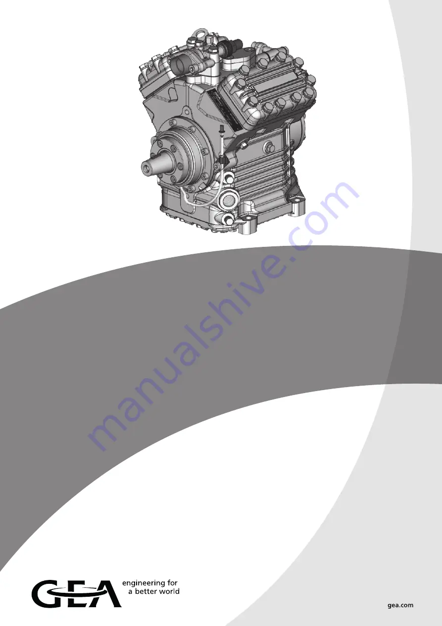
GEA Bock FK40
Maintenance manual
09665-01.2019-Gb
Translation of the original instructions
FK40/390 K
FK40/470 K
FK40/560 K
FK40/655 K
FK40/755 K
FK40/390 N
FK40/470 N
FK40/560 N
FK40/655 N
FK40/390 TK FK40/470 TK FK40/560 TK FK40/655 TK
FKX40/390 K FKX40/470 K FKX40/560 K FKX40/655 K FKX40/755 K
FKX40/390 N FKX40/470 N FKX40/560 N FKX40/655 N
FKX40/390 TK FKX40/470 TK FKX40/560 TK FKX40/655 TK


