


12
MAXIN 24e & 28e
5.5.3
Twin flue system
The Vokera twin flue system enables greater
flue distances to be achieved (see 5.4.2) than
that of the standard concentric flue system. It
can be used for horizontal or vertical
applications, however the twin flue system
must be converted to the dedicated concentric
flue kit for termination. It is essential that the
installation of the twin flue system be carried
out in strict accordance with these instructions.
Guidance notes on twin flue installation
•••••
The flue must have a fall back of 1º back to
the appliance to allow any condensate that
may form in the flue system to drain via the
condensate drain. Consideration must also
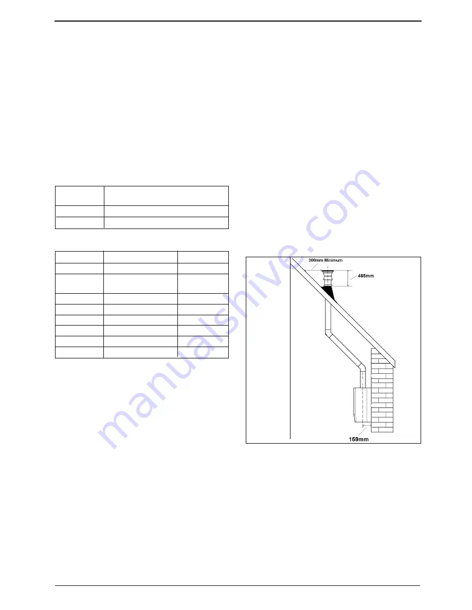
Using the dimensions given in fig. 14 as a
reference, mark and cut a 105mm hole in the
ceiling and/or roof.
Fit the appropriate flashing plate to the roof
and insert the vertical flue terminal through the
flashing plate from the outside, ensuring that
the collar on the flue terminal fits over the
flashing.
The fixing holes for the wall-mounting bracket
& jig should now be drilled and plugged, an
appropriate type and quantity of fixing should
be used to ensure that the bracket is mounted
securely. Once the bracket has been secured
to the wall, mount the appliance onto the
bracket & jig.
IMPORTANT
The vertical flue terminal is 1.0 metre in length
and cannot be cut; therefore it may be
necessary to adjust the height of the appliance
to suit or use a suitable extension.
Remove or discard the flue restrictor ring from
the appliance flue outlet (see fig. 1), if the total
Bend Reduction in maximum flue length for
each bend
45º bend
0.5 metre
90º bend
1.0 metre
Part No.
Description
Length
2359039
Vertical flue terminal
1.0 metre
0225770
Pitched roof flashing
N/A
plate
0225765
Flat roof flashing plate
N/A
2359069
750mm extension
750mm
2359079
1500mm extension
1500mm
2359049
45º bend (pair)
N/A
2359059
90º bend
N/A
0225760
Wall bracket (5)
N/A
You must ensure that the entire flue system is
properly supported and connected.
Seal the flue assembly to the wall using cement
or a suitable alternative that will provide
satisfactory weatherproofing. The interior and
exterior trim can now be fitted.
5.5.2
Concentric vertical flue
The vertical flue terminal can be connected
directly to the appliance flue outlet. Alternatively,
an extension or bend can be connected to the
appliance flue outlet if desired (see 5.4.2),
however if additional bends are fitted, a reduction
must be made to the maximum flue length (see
table below).
Reduction for bends
flue length – including the allowance for any
additional bends – exceeds 1.0 metre.
Connect the vertical flue assembly to the
boiler flue spigot using the 60mm & 100mm
clips, gaskets, & screws (supplied), ensuring
the correct seal is made. The flue support
bracket (supplied with the vertical flue kit) can
now be fitted.
If the vertical flue requires extension/s or
additional bend/s, connect the required number
of flue extensions or bends (up to the maximum
equivalent flue length) between the boiler and
vertical flue assembly (see fig. 13A).
NOTE
When cutting an extension to the required
length, you must ensure that the excess is cut
from the plain end of the extension and that
the inner (60mm) pipe is 7.5mm longer than
outer (100mm) pipe (see fig. 13A). Remove
any burrs, and check that any seals are located
properly.
You must ensure that the entire flue system is
properly supported and connected.
Vertical flue terminal and accessories
Fig. 14


