background image

Supplied By www.heating spares.co  Tel. 0161 620 6677

9

4.5.2

CONCENTRIC VERTICAL FLUE
The vertical flue terminal can be connected directly
to the appliance flue outlet. Alternatively, an
extension or bend can be connected to the
appliance flue outlet if desired (see 2.9), however
if additional bends are fitted, a reduction must be
made to the maximum flue length (see table
below).

Vertical flue terminal and accessories

Part No.

Description

Min-Max length

0225725

0225770

0225765

0225755

0225740

0225745

0225750

0225730

0225735

0225760

Vertical flue terminal

Pitched roof flashing plate

Flat roof flashing plate

350-500 telescopic extension

0,5m extension

1,0m extension

2,0m extension

45

°

 bend (pair)

90

°

 bend

Wall bracket (4)

1000 mm

N/A

N/A

350mm-500mm

500mm

1000mm

2000mm

N/A

N/A

N/A

4.5.1.1 EXTENDING THE FLUE

Connect the bend – supplied with the terminal kit
– to the top of the boiler using the boiler top
adapter (supplied, see fig. 7). The additional
bends & extensions have push-fit connections,
care should be taken to ensure that the correct
seal is made when assembling the flue system.
Connect the required number of flue extensions
or bends (up to the maximum equivalent flue
length) to the flue terminal  (see fig. 7B & 7C).

NOTE
When cutting an extension to the required length,
you must ensure that the excess is cut from the
plain end of the extension (see fig. 7B & 7C).
Remove any burrs, and check that any seals are
located properly.
You must ensure that the entire flue system is
properly supported and connected.

Fig. 7C

Reduction in maximum flue length for each bend

Reduction for bends

Bend

45

°

 bend

90

°

 bend

0,5 metre

1,0 metre

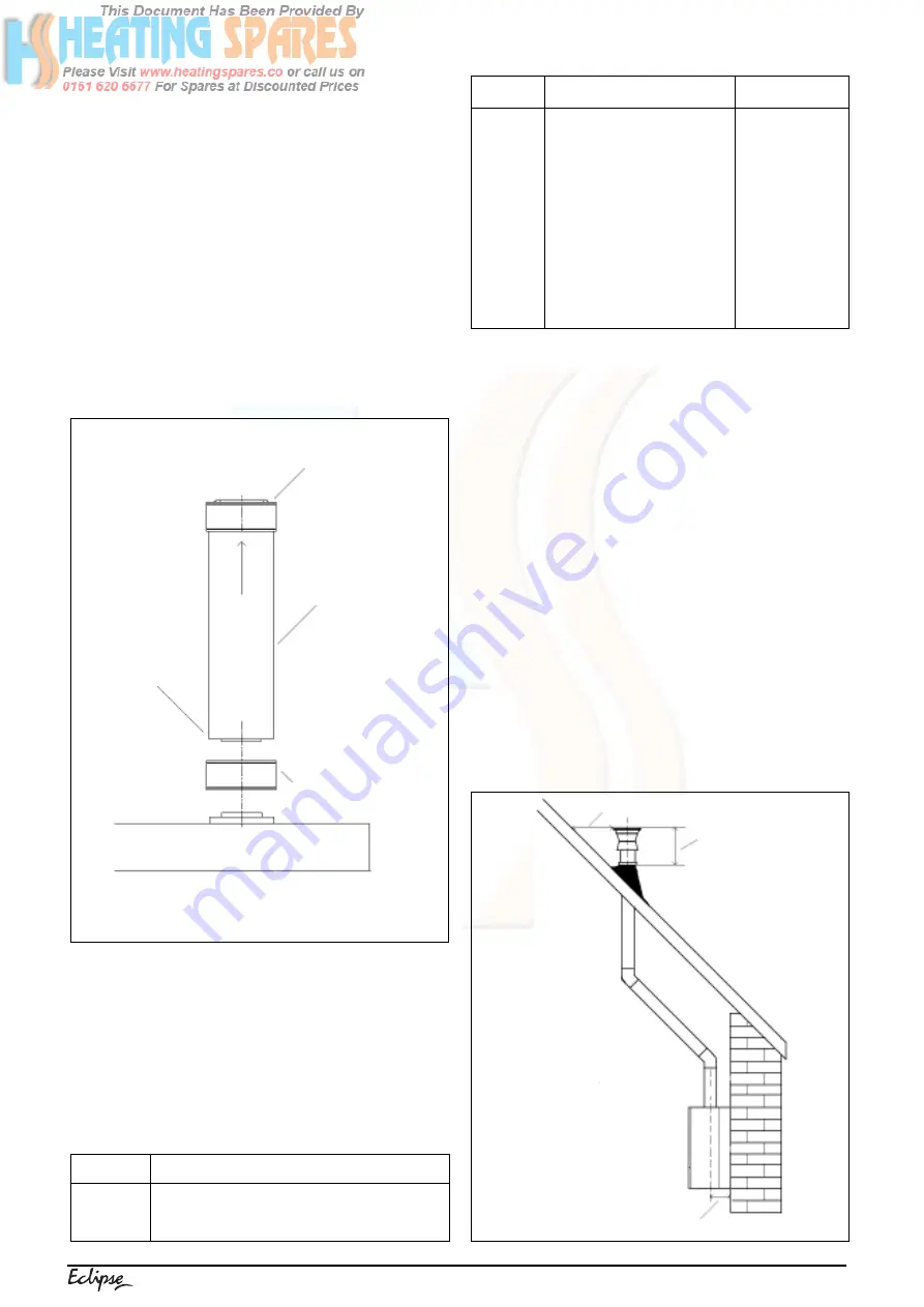
Using the dimensions given in fig. 8 as a reference,
mark and cut a 105mm hole in the ceiling and/or roof.

IMPORTANT
You must ensure that the terminal is at least
300mm from any structure or surface (see fig. 8).
The vertical flue terminal is 1,0 metre in length
and cannot be cut; therefore it may be necessary
to adjust the height of the appliance to suit or use
a suitable extension.
Encure that any horizontal sections of the flue
system have a 1

°

 fall back to the boiler (17mm per

1000mm).

Fit the appropriate flashing plate to the roof and
insert the vertical flue terminal through the flashing
plate from the outside, ensuring that the collar on
the flue terminal fits over the flashing.

The fixing holes for the wall-mounting bracket
should now be drilled and plugged, an appropriate
type and quantity of fixing should be used to
ensure that the bracket is mounted securely.
Once the bracket has been secured to the wall,
mount the appliance onto the bracket.

Fig. 8

Push-fit connection

Boiler

Extension pipe

Boiler top adaptor

Plain end

520mm

300mm minimum

139mm

Summary of Contents for Eclipse ESC

Page 1: ...Supplied By www heating spares co Tel 0161 620 6677 Installation Servicing Instructions THESE INSTRUCTIONS TO BE RETAINED BY USER ESC...

Page 2: ...esign pressure 15 5 13 Regulating the central heating system 16 5 14 Final checks 16 5 15 Instructing the user 16 Servicing Page 6 1 General 17 6 2 Routine annual servicing 17 6 3 Replacement of compo...

Page 3: ...e Vokera Eclipse ESC is a combined central heating and domestic hot water condensing boiler which by design incorporates full sequence electronic ignition circulatingpump expansionvessel safetyvalve p...

Page 4: ...speed via the electronic circuitry Depending on the load either the water temperature will continue to rise until the set point is achieved or the water temperature will fall whereby fan speed will i...

Page 5: ...mum flow rate to operate 2 5 l min 2 3 Gas pressure Maximum Inlet pressure G20 20 0 mbar Maximum gas rate 2 76 m3 h Minimum gas rate 0 80 m3 h Injector size single injector with six 3 8 mm holes 2 4 E...

Page 6: ...terminal on the same wall 1500 L Horizontally from a terminal on the same wall 300 M Horizontally from a vertical terminal to a wall 300 N Horizontally from an opening airbrick openable window etc 300...

Page 7: ...gives detailed guidance on this aspect A compartment used to enclose the appliance must be designed and constructed specifically for this purpose An existing compartment cup board may be utilised pro...

Page 8: ...located in accessible positions to facilitate draining of the appliance and all water pipes connectedtotheappliance Thedraincocksmustbe manufactured in accordance with BS 2879 3 6 4 AIR RELEASE POINTS...

Page 9: ...te outlet pipe must be connectedtothedraininaccordancewithbuilding regulations or other rules in force Fig 6 SECTION 4 INSTALLATION 4 1 DELIVERY The appliance is delivered in a heavy duty card board c...

Page 10: ...h 0225720 0225755 0225740 0225745 0225750 0225730 0225735 0225760 Horizontal flue kit for use with add bends extensions 350 500 Telescopic extension 0 5m extension 1 0m extension 2 0m extension 45 ben...

Page 11: ...g an extension to the required length you must ensure that the excess is cut from the plain end of the extension see fig 7B 7C Remove any burrs and check that any seals are located properly You must e...

Page 12: ...flashing plate Flat roof flashing plate Condensate drain kit 0 25m extension pair 0 5m extension pair 1 0m extension pair 2 0m extension pair 45 bend pair 90 bend pair Twin bracket 5 Single bracket 5...

Page 13: ...onto the male spigots of the concentric to twin converter You must ensure that the entire flue system is properly supported and connected Ensure that any horizontal sections of pipe have a 1 fall tow...

Page 14: ...ernal to the appliance are required a competent personmustundertakethedesignofanyexternal electrical circuits please refer to section 8 for detailed instructions ANYEXTERNALCONTROLORWIRINGMUST BE SERV...

Page 15: ...board Ensure that the EARTH wire is left slightly longer than the others this will prevent strain on the Earth wire should the cable become taut Do not remove the 24V link wire between terminals 2 3...

Page 16: ...Check pipe work etc for water soundness 5 6 PRE OPERATION CHECKS Before attempting to initial lighting of the appli ance the following checks must be carried out ensure all gas service valves from th...

Page 17: ...iance also has a range rating facility which can be used to limit the maximum output to central heating if required Please refer to section 7 for more details 5 12 SETTING THE SYSTEM DESIGN PRESSURE T...

Page 18: ...lla tion and commissioning in the logbook supplied with the boiler This is an important document which must be correctly completed and handed to the user Failure to install and commission the applianc...

Page 19: ...section for detailed instruction if required 6 3 REPLACEMENT OF COMPONENTS Although it is anticipated that this appliance will give years of reliable trouble free service the life spanofcomponentswil...

Page 20: ...e 4 screws that secure the PCB housing cover then remove cover After carefully taking note of all wiring connections disconnect all wiring from the PCB Locate and remove the PCB housing securing screw...

Page 21: ...gently lift the burner from its location Replaceinthereverseorder Pleasenote ensure all seals are in good condition taking care to ensure they are replaced correctly Fig 24 6 14 ELECTRODE see fig 25...

Page 22: ...seated properly NOTE It may be prudent to replace the O ring seals and valve cover gasket whenever the divertor valve assembly is disturbed 6 19 CONDENSE TRAP see fig 28 Carry out component removal p...

Page 23: ...to the rear frame The expansion vessel can now be removed Replace in the reverse order Ensure all seals are in good condition taking care to ensure they are replaced correctly 6 23 INPUT PCB STATUS PC...

Page 24: ...imits the actual flow of hot water SECTION 7 CHECKS ADJUSTMENTS AND FAULT FINDING to the taps or outlets This is to ensure that the boiler maintains a reasonable outlet temperature even if the tap or...

Page 25: ...it is to the right LED 2 shows the last two digits of the maximum fan speed press the MODE button until a fixed decimal is shown in LED 1 press and hold the MODE and buttons until L appears in LED 1 p...

Page 26: ...e correct value is displayed ontheCO2 analyser allowtimefortheanalyser to stabilise Using the procedure detailed in 7 3 5 change the fan speed momentarily from maximum to minimum then back to maximum...

Page 27: ...05 06 07 08 09 10 11 12 13 14 15 16 17 24 26 30 31 32 33 36 37 38 41 42 44 60 28 29 61 65 12 18 19 25 Reason for lockout False flame 24V short circuit No flame detected Internal fault PCB Lockout the...

Page 28: ...emetershouldreadapproximately230Vac Ifso proceed to next stage If not see 7 11 4 connect test leads between the Neutral Earth connections at the appliance input board see fig 15 Themetershouldreadappr...

Page 29: ...ity check to identify the location of the fault IMPORTANT These series of checks must be carried out before attempting any fault finding procedures on the appliance On completion of any task that requ...

Page 30: ...230V AT IS THERE PLUG M5 ON INPUT BOARD 230V AT 7 12 4 FAULT FINDING TEST 1A TEST 1A IS THERE AT TERMINALS 1 7 OF 10 14 Vdc PLUG X7 GO TO TEST 1 CHECK CONTINUITY OF RIBBON CABLE REPLACE DISPLAY PCB YE...

Page 31: ...S NO NO NO FAN FAULT DISPLAYED PRESS RESET ENSURE HEAT REQUEST DOES FAN RUN YES NO IS THERE AT RED GREY 30 35 Vdc WIRE OF FAN YES NO REPLACE FAN REPLACE PCB IS THERE AT GREY PINK 4 9 Vdc WIRE OF FAN Y...

Page 32: ...VAC 11 12 OF PLUG X2 CONTINUITY CHECK NO REPLACE PCB DOES BURNER LIGHT YES NO REPLACE RESTART TEST DOES BURNER STAY LIT YES NO NO YES IS IONISATION VOLTAGE ABOVE 2 0 Vdc REPLACE PCB SILICONE PIPE NOZ...

Page 33: ...clock bezel supplied with boiler into the aperture and secure in place with the 2 locking tabs Connect the wires to the clock as shown in fig 35 Mount the clock to the clock bezel using the screws pr...

Page 34: ...NOT BE INTERCHANGED Key R T Room thermostat F Fan P Pump S1 Flow thermistor NTC S2 Return thermistor NTC S3 D H W thermistor NTC L1 Led OK green Fig 36 L2 Led alarm blink red F1 Fusibile 2 AF F se I E...

Page 35: ...Supplied By www heating spares co Tel 0161 620 6677 33 NOTE L N E CONNECTION MUST NOT BE INTERCHANGED CONTROL SWITCHING OF TIME CLOCK AND ROOM THERMOSTAT IS 24 vdc FUNCTIONAL DIAGRAM Fig 37...

Page 36: ...input PCB terminals 2 3 Input PCB Plug X20 on display PCB PLUG or CONNECTION X7A X9 X20 DESIGNATION Connection from main PCB Unused Status LED connection PCB Input PCB Input PCB Input PCB Input PCB I...

Page 37: ...8921 10 2A INLINE FUSE 5 pcs 8968 11 DISPLAY BOARD 8918 12 INSTRUMENTAL PANEL 8346 13 QUICK PRIMER PRESSURE GAUGE 8968 14 HOLE COVER 9709 15 ADHESIVE FILM FOR INSTRUMENTAL PANEL 8349 16 PLASTIC TRADE...

Page 38: ...FUSE 3478 6 CASE CLIP 10 pcs 5588 8 WIRED TRANSFORMER 1048 9 PRESSURE GAUGE 1037 11 PRINTED CIRCUIT BOARD MTN SETTING 10022685 11 PRINTED CIRCUIT BOARD LPG SETTING 10022688 12 3 15A INLET FUSE 8969 1...

Page 39: ...14 HEATING BY PASS VALVE 1734 15 RUBBER DIAPHRAGM 6872 16 FLOW MANIFOLD FRONT PLATE 6853 17 BRASS CAP 8866 18 3 PORT VALVE SPRING 6862 19 O RING 5 pcs 6895 20 SHUTTER FOR 3 WAY 2910 21 WASHER 5 pcs 29...

Page 40: ...3 NTC SENSOR 1194 4 WASHER 10 pcs 5023 5 CONNECTIONS 8873 6 PIPE 1013 7 CONNECTION 9730 8 WASHER 10 pcs 9732 9 PIPE 9731 10 CONNECTION 10022570 11 PIPE 1192 12 SIPHON 1191 13 SILICONE TUBE 1457 14 PRE...

Page 41: ...EXCHANGER 8884 13 WASHER 9287 14 EXCHANGER LOWER INSULATING PANEL 1193 15 COVER FOR HEAT EXCHANGER 1033 16 EXCHANGER UPPER INSULATING PANEL 1016 17 ROOMSEALED CHAMBER 10022672 18 WASHER 8903 19 GLASS...

Page 42: ...AN 1018 11 SCREW 1006 12 SCREW 9292 13 PRESSURE CONNECTION 8915 14 WASHER 9299 15 MAIN BURNER JET MTN 8970 15 MAIN BURNER JET LPG 9295 16 MAIN BURNER JET SUPPORT 1195 17 GAS PIPE 10022442 18 GAS VALVE...

Page 43: ...with the relevant conversion kit the appliance engineer mode If the CO2 reading is incorrect the maximum gas pressure must be adjusted as follows Using a suitable screwdriver very slowly turn the max...

Page 44: ...442 281460 Technical Advice Tel 0141 945 6810 Spare Parts Tel 0141 945 6820 After Sales Service Tel 0870 333 0220 Vok ra Ireland West Court Callan Co Kilkenny Tel 056 55057 Fax 056 55060 Vok ra Ltd re...

Reviews: