background image

19

6.10  RETURN THERMISTOR (fig. 4 - pos. 21)

Carry out component removal procedure as described in 6.4. 

Unclip and remove the air chamber front cover. Unclip the re-

turn thermistor from the return inlet pipe. Disconnect thermistor 

electrical plug. Replace in the reverse order.

6.11  PRINTED CIRCUIT BOARD (fig. 25)

Carry out component removal procedure as described in 6.4. 

Pull the control fascia forward and lower it. Push the clips (

O

which secure the PCB cover, remove cover, after carefully tak-

ing note of all wiring connections and jumper tag configuration. 

Unhook and remove connection block (

P

). Disconnect all wiring 

from the PCB, locate and remove the PCB securing screws, 

remove the required PCB. Replace in the reverse order ensur-

ing that the position of the 2 control knobs are correctly aligned 

with the respective potentiometers on the PCB.

Ensure  that  the  correct  jumper  tag  configuration  has  been 

respected. It will be necessary to check the functioning of the 

PCB is set for the correct boiler type/application.

6.12  GAS VALVE (fig. 26)

Carry out component removal procedure as described in 6.4. 

The gas valve must be changed as complete unit. Disconnect 

the electrical plug and leads from the gas valve, slacken and 

unscrew gas valve inlet


and outlet connections. 

Please note, 

the sealing washers (

Q

) must be discarded and replaced with 

new sealing washers. Disconnect the compensation pipe (

R

). 

Unscrew gas pipe connections (

S-T

), the gas valve can now 

be removed. Replace in the reverse order. Check and adjust 

burner pressure settings.

WARNING, A GAS TIGHTNESS CHECK MUST BE CAR-

RIED OUT.

6.12.1 INJECTOR (fig. 26)

Carry out component removal procedure as described in 6.4. 

Unscrew and remove gas pipe connections (

S-T

). Locate and 

remove the injector (

U

) inside the valve. Replace in the reverse 

order. Check and adjust burner pressure settings.

WARNING, A GAS TIGHTNESS CHECK MUST BE CAR-

RIED OUT.

6.13  ELECTRODES (fig. 27)

Carry out component removal procedure as described in 6.4. 

Remove the air chamber front cover. Disconnect the electrode 

leads and ancillary wiring from their respective connectors. Re-

move the retaining screws (

V

) for electrode. Remove the spark 

ignition electrode (

W

). Remove the flame sensor electrod (

Y

).

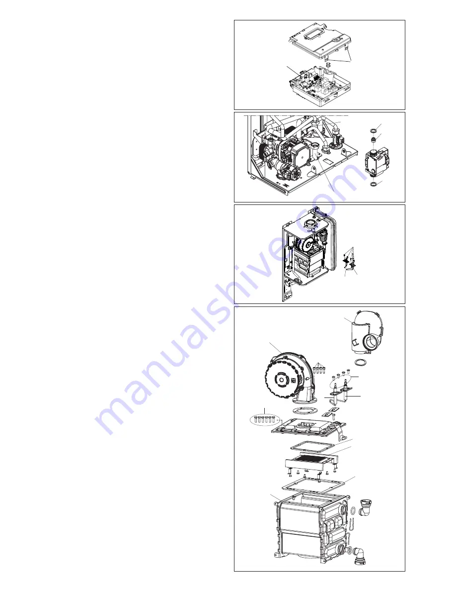
6.14 FLUE FAN & MIXER (fig. 28-29)

Carry out component removal procedure as described in 6.4. 

Remove the air chamber front cover. Locate and remove the 

gas pipe locking pin (

A1

) and swing/rotate the gas pipe away 

from the fan assembly (

B1

), (if necessary unscrew the gas 

pipe from the gas valve 

G1

). Locate and slacken the silencer 

(

H1

). Locate and remove the sense electrode. To remove the 

fan (

E1

), disconnect the electrical connections attached to the 

fan, locate and remove the four screws (

F1

). Gently ease the 

fan from its location. Replace in the reverse order. Ensure all 

seals are in good condition, taking care to ensure they are 

replaced correctly.

6.15  BURNER (fig. 28-29)

Carry out component removal procedure as described in 6.4. 

Remove the air chamber front cover. Locate and remove the 

gas pipe locking pin (

A1

) and swing/rotate the gas pipe away 

from the fan assembly (

B1

), (if necessary unscrew the gas 

pipe from the gas valve 

G1

). Locate and slacken the silencer 

(

H1

), disconnect the electrical connections attached to the 

fan. Disconnect the electrode leads and ancillary wiring from 

their respective connectors. Locate and remove the screws 

(

I1

) which secure the burner assembly in position to the heat 

exchanger (

J1

). Gently ease the fan assembly out of its location. 

Once the assembly has been removed, the burner (

K1

) can 

be withdrawn from the heat engine. Ensure the seals (

L1

) is in 

good condition, taking care to ensure it is replaced correctly. 

Replace in the reverse order.

Fig. 28

Fig. 27

V

W

Y

E1

F1

V

Y

W

H1

I1

J1

K1

L1

L1

Fig. 26

Q

Q

U

S

T

Fig. 25

P

O

Summary of Contents for Easi-Heat Plus 25C

Page 1: ...D BY USER Vok ra is a licensed member of the Benchmark scheme which aims to improve the standards of installation and commissioning of domestic hot water systems in the UK Easi Heat Plus C High effici...

Page 2: ...WATER CIRCULATION 12 3A 7 ELECTRICAL SUPPLY 12 3A 8 MOUNTING ON A COMBUSTIBLE SURFACE 12 3A 9 TIMBER FRAMED BUILDINGS 12 3A 10 INHIBITORS 12 3A 11 SHOWERS 12 3A 12 DECLARATION OF CONFORMITY 12 SECTIO...

Page 3: ...has been designed to meet and exceed the very latest standards in gas central heating technology and if cared for will give years of reliable use and efficiency Please therefore take some time to rea...

Page 4: ...ounter clockwise to reduce the temperature range 40 C 80 C for standard central heating The automatic temperature control function SARA is factory disabled To enable this function please contact the V...

Page 5: ...ntly hot enough it may be necessary to reduce the flow of water at the hot water outlet tap NOTE If the appliance fails to ignite during the ignition sequence it will enter a lockout condition Should...

Page 6: ...position To select OFF mode move the selector switch in the upper position APPLIANCE STATUS LED AND FAULT CODES Fig 3 4 WHAT IF 5 SETTING THE VOK RA Advice for homeowners Please contact Vok ra Custome...

Page 7: ...tained from Vok ra customer services When the product reaches the end of its life it should not be disposed of as solid urban waste but should be brought to a separated waste collection facility Easi...

Page 8: ...n and the boiler will perform a three minute anti cycle timer delay When the request for heat has been satisfied the appliance pump and fan may continue to operate to dissipate any residual heat withi...

Page 9: ...ght mm 792 Width mm 405 Depth mm 253 Dry weight kg 27 30 2 6 Clearances Easi Heat Plus 25C Easi Heat Plus 29C Sides 12mm Top 150mm from casing or 25mm above flue elbow whichever is applicable Bottom 1...

Page 10: ...rature boilers 37 C and for other heaters 50 C return temperature at heater inlet Seasonal space heating energy efficiency class A Water heating energy efficiency class A Parameter Symbol Value Unit P...

Page 11: ...lcony level 300 mm J From a surface or boundary facing the terminal 600 mm K From a terminal facing a terminal 1200 mm L From an opening in the car port into the building 1200 mm M Vertically from a t...

Page 12: ...c directly from the mains supply must be provided see fig 8 This method of filling complies with the current Water Supply Water Fittings Regulations 1999 and Water Bylaws 2000 Scotland If an alternati...

Page 13: ...s to be fitted on a wall of combustible material There is no requirement to protect the wall 3 9 TIMBER FRAMED BUILDINGS If the appliance is to be fitted in a timber framed building it shouldbefittedi...

Page 14: ...LOW PRESSURE SEALED SYSTEM An alternative method of filling the system would be from an independent make up vessel or tank mounted in a position at least 1 metre above the highest point in the system...

Page 15: ...talsobemadetothemaximumlength see table below when additional bends are used Reduction for additional bends Bend Reduction in maximum flue length for each bend 45 bend 1 0 metre 60 100 1 0 metre 80 12...

Page 16: ...flue length see table below Reduction for bends Bend Reduction in maximum flue length for each bend 45 bend 1 0 metre 60 100 1 0 metre 80 125 90 bend 1 0 metre 60 100 1 0 metre 80 125 Vertical flue te...

Page 17: ...no less than 20mm diameter to the outlet pipe and ensure it discharges in accord ance with building regulations or other rules in force 4 7 ELECTRICAL CONNECTIONS The boiler is supplied with a 2 metre...

Page 18: ...to remove any installation debris from the boiler prior to lighting Refill the boiler and heating system as described in 5 3 5 5 PRE OPERATION CHECKS Before attempting the initial lighting of the appl...

Page 19: ...this appliance including these instructions and explain the importance of keeping them in a safe place Explain to the user how to isolate the appliance from the gas water and electricity supplies and...

Page 20: ...nd remove the pump outlet pipe A from the pump assembly combustion chamber connection Remove the expansion pipe locking pin B from the top of the pump assembly and withdraw the flexible pipe Locate an...

Page 21: ...the reverse order Check and adjust burner pressure settings WARNING A GAS TIGHTNESS CHECK MUST BE CAR RIED OUT 6 13 ELECTRODES fig 27 Carry out component removal procedure as described in 6 4 Remove t...

Page 22: ...e carefully withdraw the by pass cartridge S1 and or DHW non return cartridge T1 Ensure all seals are in good condition taking care to ensure they are replaced correctly Replace in the reverse order e...

Page 23: ...anger DisconnectthewiringtotheDHWflowswitch Slacken and unscrew the inlet connection Unscrew the nut E2 Lift the DHW flow switch housing from its seating If necessary remove the locking pin F2 from th...

Page 24: ...e gas rate to 75 for a period of 15 minutes The speed of the fan and therefore the output of the boiler is determined by the temperature of the water sensed by the flow temperature sensor consequently...

Page 25: ...tion analysis check can easily be carried out on the appliance via the test points located on the top of the applian ce see 7 3 Operate the boiler in combustion analysis mode see 7 3 1 Insert the flue...

Page 26: ...o proceed to next stage If not see 7 7 4 connect test leads between the Neutral Earth connec tions at the appliance terminal strip The meter should read approximately 0 15Vac If so polarity is correct...

Page 27: ...particular control Further guidance on the recom mended practice for the installation of external controls can be found in CHeSS HC5 HC6 www energyefficiency gov uk 8 4 VOK RA LOWER COVER MECHANICAL...

Page 28: ...ic hot water temperature WPS Water pressure switch S E Spark electrode TSC2 Ignition transformer 3W 3 way motor F O H T Flow over heat thermostat FS Flue sensor FT Flow thermistor NTC RS Return thermi...

Page 29: ...37 0 mbar 37 0 mbar Heating maximum gas rate kg hr 1 55 1 94 DHW maximum gas rate kg hr 1 94 2 25 Minimum gas rate kg hr 0 39 0 47 Injector size 3 8 mm 3 9 Silencer flange 27 mm 29 mm CO2 maximum outp...

Page 30: ...TO MINIMUM RATE In accordance with section 7 3 set boiler to operate at minimum rate to minimum load condition Allow sufficient time for combustion to stabilise YES Is CO 350ppm and CO CO2 ratio less...

Page 31: ...ommissioning checklist completed in full To instigate the boiler guarantee the boiler needs to be registered with the manufacturer within one month of the installation To maintain the boiler guarantee...

Page 32: ...terlock Provided ALL SYSTEMS The system has been flushed and cleaned in accordance with BS7593 and boiler manufacturer s instructions Yes What system cleaner was used What inhibitor was used Quantity...

Page 33: ...gister No Record At max rate CO ppm AND CO At min rate Where Possible CO ppm AND CO Comments Signature SERVICE 04 Date Engineer name Company name Telephone No Gas safe register No Record At max rate C...

Page 34: ......

Page 35: ......

Page 36: ...1HG enquiries vokera co uk www vokera co uk www vokera ie Sales General Enquires T 0844 391 0999 F 0844 391 0998 Vok ra Ireland West Court Callan Co Kilkenny T 056 7755057 F 056 7755060 Vok ra Limited...

Reviews: