5
Pipes should be insulated to avoid heat loss and
in particular to avoid the possibility of freezing.
Particular attention should be paid to pipes passing
through ventilated areas such as under floors, loft
space, and void areas.
3.6.2
DRAIN COCKS
These must be located in accessible positions to
facilitate draining of the appliance and all water
pipes connected to the appliance. The drain
cocks must be manufactured in accordance with
BS 2879.
3.7
ELECTRICAL SUPPLY
The appliance is supplied for operation on 230V
@ 50Hz electrical supply; it must be protected
with a 3-amp fuse. The method of connection to
the mains electricity supply must allow for
complete isolation from the supply. The preferred
method is by using a double-pole switch with a
contact separation of at least 3mm. The switch
must only supply the appliance. Alternatively an
un-switched shuttered socket with a fused 3-pin
plug both complying with BS 1363 is acceptable.
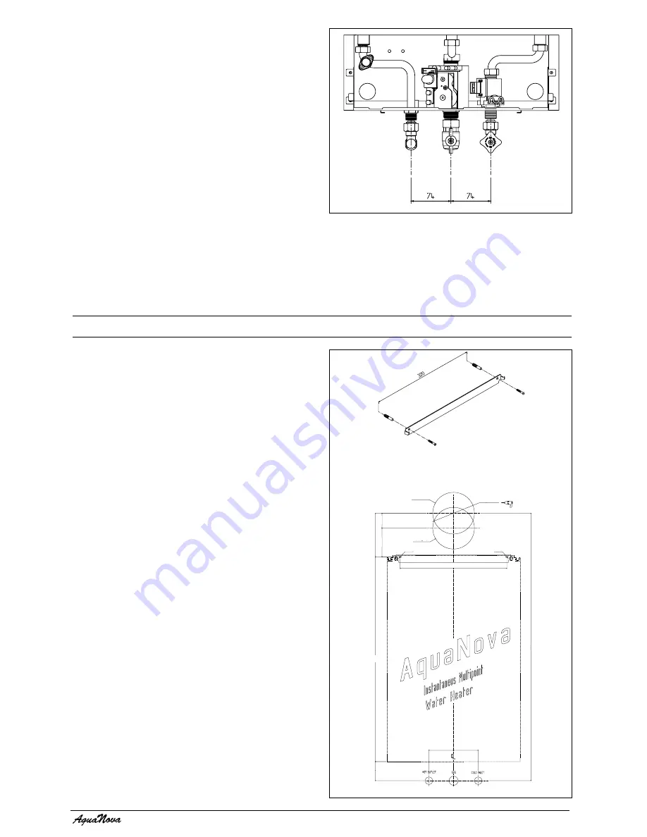
Fig. 4
4.1
DELIVERY
The appliance is delivered in a heavy-duty card-
board carton. Lay the carton on the floor with the
writing the correct way up.
4.2
CONTENTS
Contained within the carton is:
●
the appliance;
●
the wall mounting bracket;
●
template;
●
an accessories pack containing the appliance
service valves and washers;
●
the instruction pack containing the installation
& servicing instructions, user instructions and a
3-amp fuse.
4.3
UNPACKING
At the top of the carton pull both sides open – do
not use a knife – unfold the rest of the carton from
around the appliance, carefully remove all pro-
tective packaging from the appliance, and lay the
accessories etc. to one side.
4.4
PREPARATION FOR MOUNTING THE
APPLIANCE
The appliance should be mounted on a smooth,
vertical, surface, which must be capable of
supporting the full weight of the appliance. Care
should be exercised when determining the position
of the appliance with respect to hidden
obstructions such as pipes, cables, etc.
When the position of the appliance has been
decided – using the template supplied – carefully
mark the position of the wall-mounting bracket
(see fig. 5) and flue-hole (if applicable).
3.8
TIMBER FRAMED BUILDINGS
If the appliance is to be fitted in a timber framed
building, it should be fitted in accordance with
the Institute of Gas Engineers publication (IGE/
UP/7) “Guide for Gas Installations in Timber
Frame Buildings”.
SECTION 4
INSTALLATION
Fig. 5
1= centre of rear flue hole using ONLY 0225705 or 0225710 flue
2= centre of rear flue hole for ALL OTHER FLUES
ø 125
ø 6
ø 6
Type 2
Type 1
320
45
86
131
614,5
803
57,5
74
74


