background image

Vogt

®

 VT Service Manual  


6-3 

Maintenance


Air-Cooled Condenser Cleaning.


Visual inspection will indicate if dirt is accumulating and clogging 

the fin face of the condenser.  A vacuum cleaner, compressed air, or a brush may be used to remove any 
accumulation of loose dirt from the fin section of the condenser. 

For the removal of more severe accumulations of dirt or foreign materials, a detergent-type cleaner can be 
used.    This  cleaning  agent  can  be  supplied  by  your  local  refrigeration  supply  house.    Follow  the 
manufacturer’s instructions when using a liquid cleaner. 

If fins have been damaged, they should be straightened with the proper fin comb. 


Compressor Oil.


In starting and charging the unit, the oil sight glass in the crankcase of the compressor 

should be watched carefully for the first hour to make certain the proper lubrication is being maintained.  The 
oil may become low in the crankcase on an initial start-up if the electrical current has been interrupted to the 
machine, thus de-energizing the compressor crankcase heater. 

Before starting the machine again, the heater should be energized for a time period of at least two hours to 
evaporate refrigerant that may have condensed in the crankcase during the shutdown period.  If the oil level 
is low after start-up, it should begin to return after a short period of operation. 

The oil level should be checked frequently, particularly during the start-up operation, to see that a sufficient 
amount of oil remains in the crankcase.  While it is important to observe the oil splash during operation, the 
true  level  can  be  obtained  only  when  the  compressor  is  stopped.    With  the  compressor  idle,  the  oil  level 
should be between 1/2 to 3/4 of the sight glass, but not above the top of the sightglass. 

Although the machine was shipped with the oil charge, which was originally added for the test operation, it 
may be necessary to add some oil when or if new refrigerant is added to the system. 

An oil pump should be used to force any oil that may be required into the system.  Oil may be added to the 
compressor  of  all  units  through  the  compressor  oil  charging  port.    Air  should  be  purged  from  the  oil  pump 
discharge line by forcing some oil through the line before tightening the charging port. 

R22 - Dual Inhibited Suniso 3GS (Viscosity 150) or equal.   

R404A - Ultra 32 – 3MAF, Mobil EAL Arctic 22 CC or equal. 

See page 3-1 for amount.


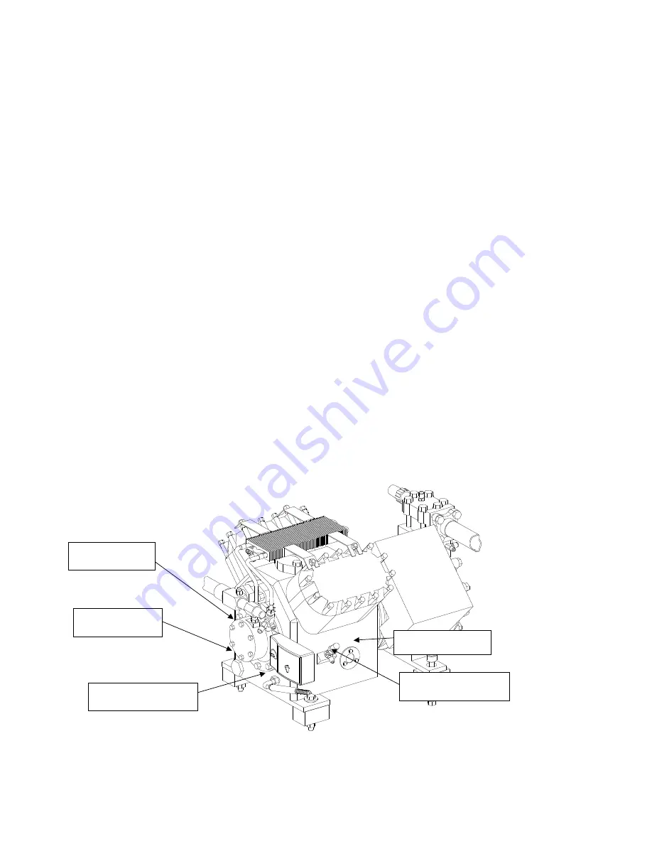
FIGURE 6-1


Copeland Discus Compressor (VT80)


Oil Sight Glass 

Oil Charging valve 

Oil Pump 

Suction Screen 

Crankcase Heater 

Oil Pump  

Summary of Contents for VT100

Page 1: ...VT Series Ice Maker Model VT40 VT60 VT80 VT100 Revision Date 1 04 12 ...

Page 2: ...sible additional expenses This manual is intended as an informational tool for the installation operation maintenance troubleshooting and servicing of this equipment If an existing situation calls for additional information not found herein we suggest that you contact your distributor first If further assistance or information is needed please feel free to contact the factory at 502 635 3000 or FA...

Page 3: ... and we pledge to support your needs and requirements after the sale This manual is provided to aid the service technician and users in the installation operation and maintenance of your equipment Before attempting to install and start the machine the installer should read and understand each section of this manual If at any time you encounter conditions that we have not addressed in this manual w...

Page 4: ...Model Number Structure 3 2 Initial Startup Section 4 Startup Procedure 4 1 Circuit Breakers Lowside Control Panel Front 4 2 Service Valve Locations 4 3 Adding Refrigerant 4 4 Suction Line Access Port 4 4 Removing Refrigerant 4 5 Electrical Controls Section 5 Explanation of Controls 5 1 Startup Standby Mode 5 1 Freeze Mode 5 1 PLC Freezer Timer 5 1 Harvest Mode 5 2 Harvest Hold Pressure Switch Incr...

Page 5: ...perature Control 8 4 PLC Programmable Logic Controller 8 5 Compressor 8 6 TXV Solenoid Valve 8 7 Adjusting TXV 8 8 Inlet Pressure Regulator 8 8 Water Tank Parts 8 9 Chopper Assembly 8 10 Evaporator Housing Covers 8 11 Freeze Cycle Piping Schematic No Hot Gas Loop 8 12 Harvest Cycle Piping Schematic No Hot Gas Loop 8 13 Freeze Cycle Piping Schematic With Hot Gas Loop 8 14 Harvest Cycle Piping Schem...

Page 6: ...T Series ice machines are built with the skill in engineering and fabrication that we have learned in over a century of ice machine manufacturing Furnished with your machine is the Certificate of Test the report of operating data that is a record of the unit s satisfactory operation on our factory test floor This manual is designed to assist you in the installation start up and maintenance of your...

Page 7: ...nd use of R404A CAUTION Inspection As soon as you receive your machine inspect it for any damage If damage is suspected note it on the shipper s papers i e the trucker s Bill of Lading Immediately make a separate written request for inspection by the freight line s agent Any repair work or alteration to the machine without the permission of the Vogt Ice can void the machine s warranty You should a...

Page 8: ... valve before disconnecting the cylinder Loosen the union in the refrigerant charging line carefully to avoid unnecessary and illegal release of refrigerant into the atmosphere CAUTION Immediately close system charging valve at commencement of defrost or thawing cycle if refrigerant cylinder is connected Never leave a refrigerant cylinder connected to system except during charging operation Failur...

Page 9: ... Line Discharge Liquid Return VT40 1 3 8 OD 7 8 OD 5 8 OD N A N A VT60 1 1 8 OD 7 8 OD VT80 1 5 8 OD 1 1 8 OD 7 8 OD VT100 1 3 8 OD Note Split systems will be supplied with Rota lock adapters to connect the highside to the lowside TABLE 2 3 Refrigerant Line Sizes Machine Clearances A minimum three 3 feet of clearance is recommended around entire ice machine This will provide sufficient area for se...

Page 10: ...ll valves and remove Schrader valve core prior to brazing Pressure test piping for leaks Evacuate lines to 500 microns prior to starting machine Chute Location Using drawing and table below determine ice machine location so that it is centered on bin Place ice machine on ice storage unit and bolt in place Machine must be level front to back and side to side for proper operation FIGURE 2 2 Ice Chut...

Page 11: ...T100 Usage Gallons 100 lbs of Ice 12 12 12 12 Flow rate Gallons minute 0 38 0 54 0 67 0 80 Flow rate Gallons hour 22 5 32 5 40 0 48 0 Water Tank Capacity Gallons 6 7 Note Water usage and flow rates base on 70 F water with no blowdown TABLE 2 4 MakeUp Water Requirements Flow Rates Makeup water water tank drain and water tank overflow are FPT connections ...

Page 12: ...itch must be provided near the condensing unit of the ice machine Connect 3 phase power to compressor contactor L1 L2 L3 for operation of the VT ice machine and its controls If one phase leg of the 3 phase power is higher or lower Wild it should be connected to terminal L2 Connect the Ground wire to the Ground terminal provided Electrical Data VT40 VT60 VT80 VT100 Volts Phase Hertz 208 230 3 60 20...

Page 13: ...side control panel terminal block to the condensing unit highside control panel terminal block TABLE 2 6 Lowside to Highside Wire FIGURE 2 6 Lowside Unit Terminal Block Note Machine is supplied with a remote on off connection on the lowside terminal block If a remote On Off switch is used remove jumper between 18 X1 and connect switch to these terminals Number of wires Wire Size AWG Wire 5 16 Red ...

Page 14: ...te condensers are trapped internally A trap leaving the compressor is not necessary On vertical runs a short radius P trap should be installed every 15 to 20 of vertical rise to facilitate oil flow Horizontal runs should be sloped in direction of refrigerant flow 1 for every 20 of run The condenser should be securely mounted in a place capable of sustaining its weight FIGURE 2 8 Condenser Piping V...

Page 15: ... lock Adapter Note Rota lock adapters supplied with machine Note Rota lock male adapter on ice machine Must solder with 45 silver solder Liquid return from Air Cooled Condenser 7 8 line Discharge gas to Air Cooled Condenser VT80 1 1 8 VT100 1 3 8 Female Rota lock Adapters 12A2396A0701 for 1 12 F x 7 8 Sweat Solder Return Line from condenser 12A2396A0601 for 1 12 F x 1 3 8 Sweat Solder Discharge to...

Page 16: ... panel to the Air Cooled condenser control panel 208 230V 460V FIGURE 2 11 VT80 VT100 Remote Air Cooled Condenser Wiring Note Fan control pressure switch is located in air cooled condenser control panel on VT80 VT100 s with remote condensers On VT40 s and VT60 s fan control pressure switch is location on condensing unit highside To Ice Machines condensing unit control panel To Ice Machines condens...

Page 17: ...ne 12A2396A0601 1 3 8 IDS X 1 3 4 12Thrd 12A2600T03 Suction Line Suction Line 12A2396A0701 7 8 IDS X 1 1 4 12Thrd 12A2600T01 Liquid Hot Gas line Liquid Line TABLE 2 5 Rota lock Adapters Note See Refrigerant Line Size TABLE 2 3 for line sizes Rota lock Adapter 1 3 8 IDS X 1 3 4 12 Threads 1 1 8 IDS X 1 1 4 12 Threads 7 8 IDS X 1 1 4 12 Threads Note Rota lock fittings supplied for both lowside and h...

Page 18: ...Vogt VT Service Manual 2 11 Installation Instructions FIGURE 2 13 VT60 Condensing Unit Connections FIGURE 2 14 VT40 Condensing Unit Connections Control Panel Control Panel ...

Page 19: ...ons Storing Ice When storing ice in a bin make sure the bin control sensor is mounted in the bin properly The sensor should be mounted on the right side of the bin approximately 8 12 from the top of the bin FIGURE 2 15A Bin Control Sensor Installation ...

Page 20: ...en into account when locating the bin thermostat sensor or other bin level control and when calculating the normal bin capacity If the ice is spread out by hand in the bin for maximum storage capacity make sure a hazard is not created by allowing ice to back up into the chute and jamming the cutter Always allow enough room below the chute for at least one harvest VT40 25 30 lbs cycle VT60 VT80 35 ...

Page 21: ...2 14 Vogt VT Service Manual Installation Instructions Blank ...

Page 22: ...an Motors HP 2 1 2 HP Voltage 208 230 V FLA Total for both motors 8 4 A 8 2 A 8 4 A 8 6 A Field Connections Remote Condensing Units Only Suction 1 3 8 ODS 1 3 8 ODS N A N A Hot Gas 7 8 ODS 1 1 8 ODS 1 1 8 ODS 1 1 8 ODS Liquid 5 8 ODS 7 8 ODS 7 8 ODS 7 8 ODS General Info Sight Glass Sporlan SA 15U SA 17S SA 17S SA 17S Filter Drier Sporlan C 415 RC 4864 RC 4864 RC 4864 Refrigerant Charge 16 lbs 32 l...

Page 23: ... Compressor F 5 HP G 7HP 3cyl 2120 CFH H 7HP 4cyl 2380 CFH J 10HP K 12 5HP Revision Level A letter assigned to indicate major revisions within any one family series Refrigerant F R22 H R404A Electrical Codes 26 208 230 3 60 46 460 3 60 25 200 3 50 45 400 3 50 35 380 3 50 21 230 1 60 Product Variation Codes A number or letter designator assigned to specific variations within a family 01 CE Approved...

Page 24: ...e in the on position Figure 4 2 Note Control Power Light will be ON when power is supplied to Lowside At completion of above eight 8 items machine is ready to run Place selector switch in Clean position and check water flow If the pump does not come on press the green Manual Harvest button Place selector switch in Ice position and press Manual Harvest button The machine will start in a harvest mod...

Page 25: ...chines FIGURE 4 3 Lowside Control Panel Front Selector Switch Ice Off Clean Manual Harvest Start Lowside unit control panel Condensing unit control panel 10 A 15 A CB1 Lowside CB2 Condenser Fans Control Circuit Power Light Light will be on if power is being supplied from the Highside ...

Page 26: ...s VT40 Compressor Suction Service Valve Hot Gas Line Ball Valve Receiver Service Valve Compressor Discharge Service Valve VT60 Compressor Suction Service Valve Hot Gas Line Ball Valve Receiver Service Valve Compressor Discharge Service Valve Liquid Line Ball Valve Liquid Line Ball Valve ...

Page 27: ... suction port or the access fitting on suction line See Figure 4 6 If the glass clears in less than 8 seconds the unit is overcharged Remove refrigerant from system following EPA standards Note Do not charge to a full sightglass Do not charge in a harvest cycle If packaged unit is totally out of refrigerant add amount specified on machines nameplate FIGURE 4 6 Access port for adding refrigerant Co...

Page 28: ...reclaimed from the liquid line VT80 VT100 access port on liquid line ball valve VT60 access port on receiver rota lock valve VT40 access port in liquid line FIGURE 4 7 Access Fitting for Removing Refrigerant Note Follow all EPA regulations and guidelines when handling refrigerant VT60 VT80 VT100 VT40 Liquid line Ball Valve with access port Receiver Service Valve rotalock valve with access port Liq...

Page 29: ...4 6 Vogt VT Service Manual Initial Startup Blank ...

Page 30: ...chine is in the Start Up Mode the Fault Indicator light will remain on will not be blinking CAUTION If the power has been turned off to the machine make sure the compressor crankcase is warm and there is no liquid refrigerant in with the oil before restarting the unit CAUTION Standby Mode The standby mode is a decision making mode It monitors the position of all the various switches in the control...

Page 31: ... Long Harvest Cycle Safety The PLC monitors harvest cycle time If the suction pressure does not reach the HH pressure switch set point within 3 minutes the machine will shut down and go to the Fault Mode NOTE If the Selector Switch switch is in the Off position or the bin control is satisfied the machine will complete the Freeze Harvest and Pumpdown cycle before shutting off standby mode Machines ...

Page 32: ...n mode the machine can be returned to ice making mode by putting the Selector Switch in the Ice position and pressing the Manual Harvest button Fault Mode The VT Series is equipped with a PLC programmable logic controller that controls all aspects of the operation One of the functions of the PLC is to shut down the machine when a problem arises and send a signal to the fault indicator light locate...

Page 33: ...in series 1 Liquid Feed Solenoid R404A machine only 2 Harvest Hold HH Pressure Switch 2 Compressor 3 Start Manual Harvest Switch 3 N A 4 Clean Switch 4 Water Pump 5 High Pressure safety off when tripped 5 Cutter D valve Defrost loop valve or 6 Low Pressure safety off when tripped Suction Stop valve VT80 VT100 7 Oil Safety Compressor OL VT80 VT100 FIGURE 5 4 PLC Inputs Outputs PLC FX1s PLC FXos ...

Page 34: ...Vogt VT Service Manual 5 5 Electrical Controls FIGURE 5 5 Standard Complete Electrical Schematic 208 230V Air Cooled ...

Page 35: ...5 6 Vogt VT Service Manual Electrical Controls FIGURE 5 5A CE Rated VT100 Electrical Schematic 200 220V 400 440V Water Cooled ...

Page 36: ...Vogt VT Service Manual 5 7 Electrical Controls FIGURE 5 6 Air Cooled Condenser Wiring 200 240V 400 460V ...

Page 37: ... Push Pull P 12A7516E23 Pump Motor Contactor PB1 12A7500E56 Manual Harvest Start Button 12A7500E75 Contact Block 1 N O for Manual Harvest Button PLC 12A7536M01 Programmable Logic Controller HH 12A2117B03 Harvest Hold Pressure Switch Open on Rise SS 12A7500E61 3 Position Selector Switch 12A7500E73 Contact Block 2 N O for Selector Switch TB N A Terminal Block 1LT 12A7520E33 Machine Fault Indicator L...

Page 38: ...Vogt VT Service Manual 5 9 Electrical Controls FIGURE 5 8 Standard Condensing Unit Electrical Schematic 208 240V Air Cooled ...

Page 39: ...or Contactor 43Amp 12A7516E30 VT60 80 100 Compressor Contactor 72Amp 12A7518E30 Auxiliary Contact 1 N O 1 N C CB1 12A7515E18 Lowside Circuit Breaker 2 pole 10Amp CB2 12A7515E19 AC Fan motors Circuit Breaker 2 pole 15Amp TB N A Terminal Block FIGURE 5 8A Standard 208 240V Condensing Unit Control Panel Air Cooled ...

Page 40: ...Vogt VT Service Manual 5 11 Electrical Controls FIGURE 5 9 CE Rated VT100 200 220V 400 440V Condensing Schematic Water Cooled ...

Page 41: ...ISCONNECT HANDLE 1 12A7518E30 AUX CONTACT 1 NO 1 NC 1 12A2790D07 DISCONNECT 63A DOOR MNT 1 CB1 12A7515E18 CIRCUIT BREAKER 10A 2 POLE 1 400 440V MACH 200 220V MACH 12A2790D11 DISCONNECT 100A DOOR MNT 12A7515E35 CIRCUIT BREAKER 8A 2 POLE 200 220V MACH 400 440V MACH FU1 12A7504E12 FUSE 10A 600V TD CLASS CC 3 CB2 12A7515E19 CIRCUIT BREAKER 10A 2 POLE 1 FU3 AC 400 440V ONLY AC 200 220V MACH PLF 12A7527...

Page 42: ...nliness 6 Unusual noises Why When you make these simple observations on a daily basis you insure the smooth production of ice for your facility When you are aware of the proper operating conditions and observe them on a daily basis changes in these conditions can alert you to changes in the operation of the machine which may require maintenance long before a service situation arises Note To Manage...

Page 43: ...igerant charge okay high low Leak checked system ______ leaks found repaired Compressor oil level i e 1 4 1 2 3 4 low high PSIG low pressure switch set 10 psi PSIG high pressure switch set 300 psi R22 350 psi R404A Bin stat s installed and operate properly Make up water float valve adjusted okay _________ Suction PSIG at end of freeze ________ Suction PSIG during harvest high low ________ PSIG Dis...

Page 44: ...orate refrigerant that may have condensed in the crankcase during the shutdown period If the oil level is low after start up it should begin to return after a short period of operation The oil level should be checked frequently particularly during the start up operation to see that a sufficient amount of oil remains in the crankcase While it is important to observe the oil splash during operation ...

Page 45: ...ar housing Use Mobile 600W cylinder oil or equal FIGURE 6 2 Gear Reducer Water Distributor At times it may be necessary to clean the plastic water distributor Remove the water supply tube by removing the hose clamp The water distributor may be soaked in ice machine cleaner Make sure all holes are free of dirt and calcium buildup FIGURE 6 3 Water Distributor Gear Reducer Gear Reducer Vent Plug 1 Tu...

Page 46: ...or light located on the control panel door FIGURE 7 1 Lowside Control Panel Front Description Switch Reset Auto or Manual 1 Low Suction Pressure Auto 2 High Discharge Pressure Manual 3 Low Oil Pressure Manual 4 Long Harvest Cycle N A 5 Chopper Motor Fault N A 6 Pumpdown Fault N A Solid Power Failure N A TABLE 7 1 PLC Fault Codes Control Power Light if the machine is shut off and the Control Power ...

Page 47: ...ty Compressor OL VT80 VT100 TABLE 7 2 PLC Inputs Outputs FIGURE 7 3 PLC FX1s Damaged Bin Control Sensor If the machine is not running and it uses the electronic temperature control to shut the machine off when the bin is full one of the first things to check is the Bin Control sensor If the sensor is bad or has been damaged EP will be displayed See 8 3 for more details FIGURE 7 3 Electronic Bin Co...

Page 48: ...nse after March 2011 Machines are equipped with a compressor protection device that opens in the event compressor temperature or amperage reaches an extreme that could damage compressor The device automatically resets after compressor has cooled CoreSense must be reset Note On VT80 V100 Only Note This sensor is in series with the oil pressure safety switch Fault 3 can be either compressor motor ov...

Page 49: ...ior to harvest 9 Loss of water pressure 10 Defective hot gas solenoid valve 11 TXV not adjusted properly or functioning properly Ice freezing too far up tube Note If ice is freezing too high onto the top flange holding the evaporator the ice may not drop from the evaoprator tubing See page 8 6 for adjusting TXV Clearing a freeze up can be accomplished by placing On Off Clean selector switch in the...

Page 50: ...r module Sentronic CoreSense 2 Clogged oil pump suction screen 3 Low compressor oil 4 Low compressor superheat Compressor Runs But Condenser Fan Does Not 1 Faulty fan cycle switch 2 Faulty fan motor 3 Blocked fan blade 4 Electric interruption to condenser circuit breaker located in condensing unit control panel Compressor Will Not Run Water Pump Runs 1 Open compressor overload on VT 40 VT 60 only ...

Page 51: ...7 6 Vogt VT Service Manual Troubleshooting Blank ...

Page 52: ...to the water tank via float valve Freeze time and harvest time are controlled by a Programmable Logic Controller PLC In freeze cycle the liquid feed valve is open R404A machines only and the compressor and water pump are on At the end of the Freeze cycle the PLC initiates the Harvest cycle were the hot gas solenoid valves and chopper motor are energized and the water pump is turned off and liquid ...

Page 53: ...w pressure switch for 90 seconds Settings Cut out Off 10 PSIG R22 R404A Cut in On 20 PSIG R22 R404A Fan Control Switch 12A2117F05 Penn This switch cycles the condenser fan motors to maintain proper discharge pressure Settings Cut in On 220 PSIG R22 250 PSIG R404A Cut out Off 200 PSIG R22 230 PSIG R404A Harvest Hold Switch 12A2117B03 Penn 12A2117B03CE Danfoss for CE machines This switch stops harve...

Page 54: ...ule in 4D 6D compressors Note 2D 3D compressor will still have Internal Line Break overload protection The oil pressure monitoring portion of the CoreSense will act very similar to the Sentronic Oil Pressure Safety switch A current transformer CT in the compressor junction box determines when the compressor is running and starts monitoring oil pressure The CoreSense module has power applied at all...

Page 55: ...drops to 38 F and come on when temperature reaches 40 F Note The sensor will automatically exit the programming mode if no keys are depressed for a period of thirty seconds Any settings that have been input to the control will be accepted at that point FIGURE 8 4 Electronic Temperature Control Part 12A 2117G09 Error Messages E1 Appears when either the up or down key is pressed when not in the prog...

Page 56: ...mode Only one mode is active at a time FIGURE 8 5 PLC Programmable Logic Controller Description Description Inputs 0 Current Sensing Relay chopper Outputs 0 Fault Indicator light 1 On Selector Switch Bin Control 1 Liquid Feed Solenoid R404A machines only 2 HH Pressure Switch 2 Compressor 3 Manual Harvest Start Button 3 N A 4 Clean Switch 4 Water Pump 5 High Pressure Safety Switch 5 Chopper Hot Gas...

Page 57: ...KE TFC 100 VT 80 10 HP R22 12A2110A122 4DL3F63K0 TSK 253 R404A 12A2110A128 4DL3F63KE TSK 253 VT100 12 1 2 HP R22 12A2110A125 4DT3F76K0 TSK 253 R404A 12A2110A129 4DT3F76KE TSK 253 Crankcase Heater 100 W insert type 12A7509E12 518 0028 01 Oil Pressure safety switch Sentronic R22 R404A 12A2117A05 585 1066 02 TABLE 8 2 Compressor Compressor Parts Oil Sightglass Discharge Service Valve Suction Service ...

Page 58: ...8 valve B19S after 4 2011 12A4200A0708 Sporlan 5 8 N C Rebuild Kit 12A4199V38 Sporlan 7 8 N C Rebuild Kit for B25S valve 12A4199V39 Sporlan 7 8 N C Rebuild Kit for B19S valve 12A4199V43 Sporlan Inlet Pressure Regulator Valve 1 1 8 Regulator valve 12A4200N0903 Parker TXV R22 Machines 12A4200C0305 Sporlan R404A Machines VT40 60 80 12A4200C0320 Sporlan VT100 12A4200C0321 Sporlan TABLE 8 3 TXV Regulat...

Page 59: ...m out Do this by turning the TXV stem counter clockwise looking up at the valve stem Note Check expansion valve inlet strainer before opening valve Clean strainer if necessary Open TXV turn at a time Observe several cycles before making further changes FIGURE 8 7 Adjusting TXV Inlet Pressure Regulator This regulator valve is used on the split VT40 split VT60 VT80 and VT100 The purpose of this valv...

Page 60: ...proved machine Water Pump Cover Plastic 12A2150VT01 Float Valve Cover Plastic 12A2150VT02 VT60 VT80 VT100 Ice Chute Cover Plastic 12A2145VT02 VT40 Ice Chute Cover Plastic 12A2145VT04 Float Valve not shown 12A4200H0401 VT60 VT80 VT100 Water Distributor 12A2185D02 VT40 Water Distributor 12A2185D01 Tubing 1 ID 12A4181T04 ...

Page 61: ...ngs 12A2020M19 3 Bracket for Gear Reducer 19T4001S0740 4 Gear Reducer 5 1 12A4030R14 5 Motor HP 3600 RPM 56C Face 208 230V 1 Phase 50 60Hz 12A2900M0511 12A2900M0511CE CE approved 6 Plate UHMW for Gear Reducer Bracket 19T2150VT01 FIGURE 8 10 Chopper Assembly 4 1 2 3 5 6 Bolts welded on Evaporator Housing Nuts welded on gear reducer bracket Gear reducer vent plug ...

Page 62: ...vaporator housing cover 19T4001S0762 19T4001S0766 VT40 Upper Evaporator housing cover 19T4001S0764 19T40001S0766 CAUTION Never Operate Machine with Lower Evaporator Housing Cover Removed Disconnect Power to machine before removing lower evaporator cover VT60 VT80 VT100 Lower Evaporator housing cover 19T4001S0763 VT40 Lower Evaporator housing cover 19T4001S0765 ...

Page 63: ...8 12 Vogt VT Service Manual Service Operations FIGURE 8 12 Freeze Cycle Schematic Skid mounted Package VT40 VT60 ...

Page 64: ...Vogt VT Service Manual 8 13 Service Operations FIGURE 8 13 Harvest Cycle Schematic Skid mounted Package VT40 VT60 ...

Page 65: ...8 14 Vogt VT Service Manual Service Operations FIGURE 8 14 Freeze Cycle Schematic w Defrost Loop Valve Split System VT40 VT60 ...

Page 66: ...Vogt VT Service Manual 8 15 Service Operations FIGURE 8 15 Harvest Cycle Schematic w Defrost Loop Valve Split System VT40 VT60 ...

Page 67: ...8 16 Vogt VT Service Manual Service Operations FIGURE 8 16 Freeze Cycle Schematic w Suction Stop Valve VT80 VT100 ...

Page 68: ...Vogt VT Service Manual 8 17 Service Operations FIGURE 8 17 Harvest Cycle Schematic w Suction Stop Valve VT80 VT100 ...

Page 69: ...CUTTER MOTOR CIRCUIT BREAKER 2 POLE 10 AMP CB1 Control Circuit Low Side 12A7515E19 1 CONDENSER FAN CIRCUIT BREAKER 2 POLE 15 AMP CB2 Control Circuit Condensing Unit 12A2117A05 1 SENTRONIC OIL PRESSURE SAFETY CONTROL 12A2117B08 1 LOW PRESSURE CONTROL 20 100 1 4 SAE 36 CAP TUBE 12A2117H01 1 HIGH PRESSURE CONTROL 50 450 1 4 SAE 36 CAP TUBE 12A2117F05 1 CONDENSER FAN CONTROL SWITCH 12A2117G09 1 ELECTR...

Page 70: ... 240V 50 60HZ Condensing Unit 12A2110A117 1 VT40 COMPRESSOR R22 3DB3F33K0 TFC 100 208 230 3 60 5 5HP 12A2110A130 R404A 3DB3F33KE TFC 100 208 230 3 60 5 5HP 12A2110A110 1 VT60 COMPRESSOR R22 3DS3F46K0 TFC 100 208 230 3 60 7HP 12A2110A131 R404A 3DS3F46KE TFC 100 208 230 3 60 7HP 12A2110A122 1 VT80 COMPRESSOR R22 4DL3F63K0 TSK 253 208 230 400 460 10HP 12A2110A128 R404A 4DL3F63KE TSK 253 208 230 400 4...

Page 71: ...8 20 Vogt VT Service Manual Service Operations Blank ...

Page 72: ...lly shows the AB BC CA line voltages If the unit is waiting on a timer that timer will be displayed The timer display may be switched off by pressing SELECT The LCD will then display the normal AB BC CA line voltage pairs Pressing the SELECT button once shows the contactor load side voltages if the load side option is connected The display automatically returns to the display of line side voltage ...

Page 73: ...essing the up and down arrows selects off default or on The load side of the contactor must be connected to the load terminals of the DTP 3 to use this option Display of fault memories MEM flashes Pressing up or down displays the last fault conditions that took the unit off line The first 25 faults are recorded The top number displayed represents the fault memory The middle number represents the t...

Page 74: ...hines will have an Emergency Stop button Remote Switch Box Parts PART DESCRIPTION R PB1 12A7500E56 PUSH BUTTON MOMENTARY GREEN 12A7500E75 CONTACT BLOCK 1 N O W MOUNTING LATCH R PB2 12A7500E130 E STOP PUSH PULL RED CE MACHINE ONLY 12A7500E76 CONTACT BLOCK 1 N C W MOUNTING LATCH CE MACHINE ONLY R SS 12A7500E61 3 POS SELECTOR SWITCH OPERATOR 12A7500E73 CONTACT BLOCK 2 N O W MOUNTING LATCH R 1LT 12A75...

Page 75: ...9 4 Vogt VT Service Manual Additional Product Information FIGURE 9 2A Standard Electrical Schematic 208 230V With Remote Switch Box ...

Page 76: ...Vogt VT Service Manual 9 5 Additional Product Information FIGURE 9 2B CE Approved Electrical Schematic 208 230V With Remote Switch Box ...

Reviews: