background image

15

Setting the Frequencies Manually

If the UHF-8900 is used in an area with heavy RF interference, it may be beneficial to set the frequencies manually. 

Please refer to the Advance Operation page to determine which frequencies to use for that area.

Note: Please read through the steps before attempting to sync the microphones. The module menus have a 4 second timeout 
period where if a button is not pressed within that time the module will 
revert back to the frequency information page.

MANUAL SETUP

Setting up the frequencies manually

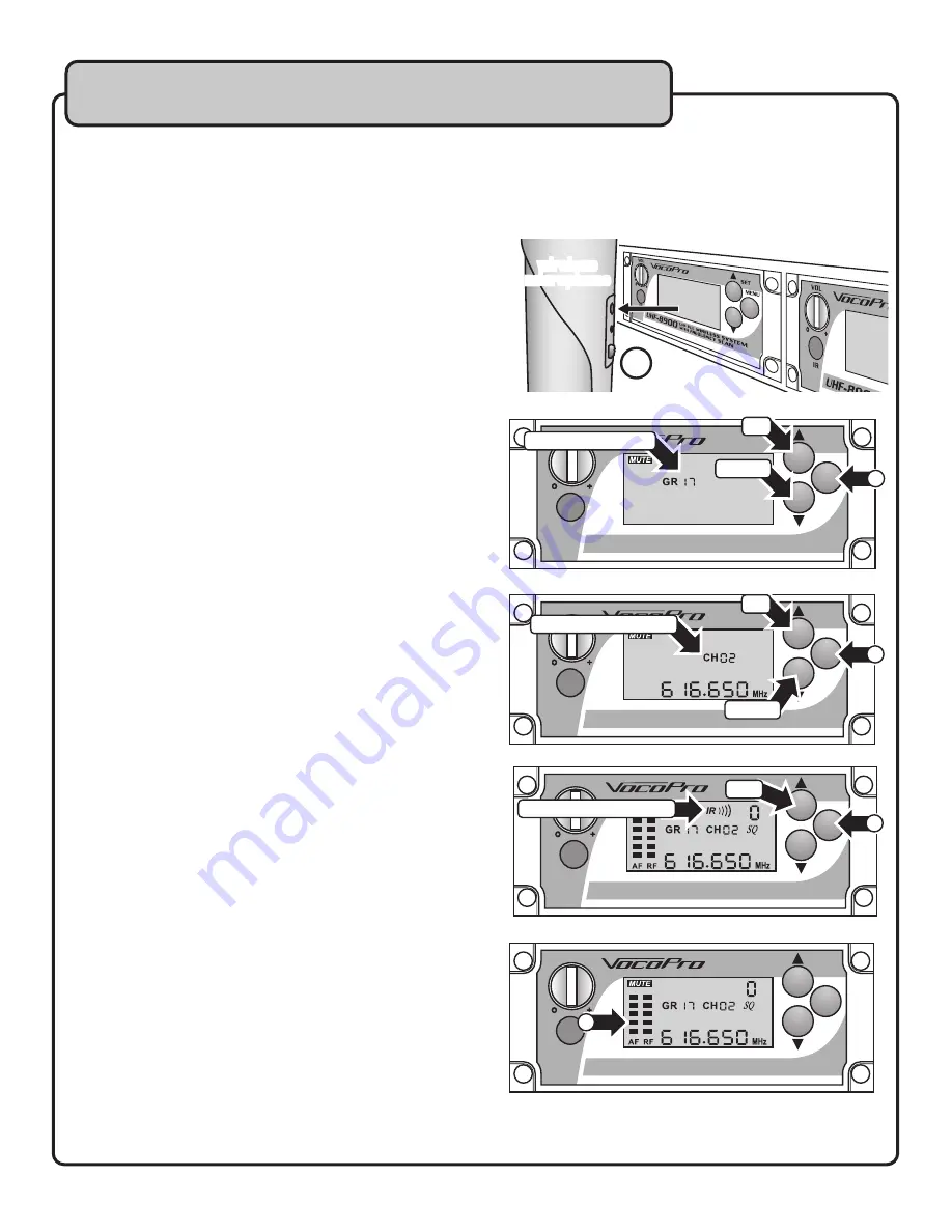
1 .  Prepare the System: Ensure the receiver base, the desired 

module to be paired, and the desired microphone to be 

paired, are all powered on.

2 .  Identify the IR Sensors: Locate the IR sensor on both the 

microphone and module . 

A.) Microphone - The IR sensor is located just above the  

ON/OFF switch. 

B.) Module - The IR sensor is located directly below the 

module volume knob.

3 .  Align the IR Sensors: Position the microphone so that the 2 IR 

sensors are level and within 3-5 inches of one another.

4 .  Select a Group (GR): Press the Menu button on the desired 

module once (1x). This will display the symbol “GR” on the 

LCD. With the “GR” symbol displayed, use the UP/DOWN 

buttons to select the desired group .

5 .  Select a Channel (CH): Press the MENU button on the desired 

module twice (2x). This will cycle the menu past the “SCAN” 

screen and enter the Channel (CH) selection screen; this 

will display the symbol “CH” on the LCD. With the CH symbol 

displayed, use the UP/DOWN buttons to select the desired 

channel .

6 .  Sync Microphone: Press the MENU button once (1x) to enter 

IR mode; this will display the symbol “IR” on the LCD. With the 

IR symbol displayed, press the SET button to communicate the 

desired frequency to the microphone. This will display waves 

emanating from the “IR” symbol, when the waves disappear 

the screen will display the chosen frequency, as well as the AF 

and RF reception bars for that channel .

7 .  Test the Mic: Speak into the microphone to ensure sound is 

being produced and transmitted . The AF bars on the LCD 

should register as the microphone is spoken into.

Note: Once the microphone and module are synced, there will be a 
5 second delay in audio when the microphone is powered on. This is 
normal.

8 .  Repeat the Process: Repeat steps 3-7 for each of the 

remaining microphone and modules .

Setting up the Microphones

SET

UHF-8900

IR

VOL

UHF PLL WIRELESS SYSTEM

WITH FREQUENCY SCAN

MENU

4

GROUP SYMBOL

UP

DOWN

SET

UHF-8900

IR

VOL

UHF PLL WIRELESS SYSTEM

WITH FREQUENCY SCAN

MENU

5

CHANNEL SYMBOL

UP

DOWN

SET

UHF-8900

IR

VOL

UHF PLL WIRELESS SYSTEM

WITH FREQUENCY SCAN

MENU

IR PROGRAM MODE

6

SET

3

wireless

microphone

SET

UHF-8900

IR

VOL

UHF PLL WIRELESS SYSTEM

WITH FREQUENCY SCAN

MENU

7

Summary of Contents for UHF-8900

Page 1: ...o w n e r s m a n u a l UHF 8900 UHF PLL WIRELESS MIC SYSTEM WITH FREQUENCY SCAN...

Page 2: ...a Lifetime 6 Features 7 Getting Connected 8 Descriptions and Functions 10 Setting up the Microphones 13 Re syncing the Microphones 16 Using the Wireless Mics 17 Basic Operations 18 Advanced Operations...

Page 3: ...cluding amplifiers that produce heat 10 Power Sources The appliance should be connected to a power supply only of the type described in the operating instructions or as marked on the appliance 11 Grou...

Page 4: ...e place for future reference 2 Install your unit in a cool dry clean place away from windows heat sources and too much vibration dust moisture or cold Avoid sources of hum transformers motors To preve...

Page 5: ...urtiss Court La Verne CA 91750 Toll Free 800 678 5348 TEL 909 593 8893 FAX 909 593 8890 VocoPro Company Email Directory Customer Service General Information info vocopro com Tech Support techsupport v...

Page 6: ...ay attention to the different levels in various recordings Taking a minute to do this now will help to prevent hearing damage or loss in the future After all we want you listening for a lifetime Used...

Page 7: ...150 wireless frequencies available LCD display shows frequency and other info 19 rack mountable chassis uses just 2 rack spaces Independent power knob and volume control per channel 8 balanced XLR ou...

Page 8: ...8900 3 Connect the other end of the XLR cable to the desired input on your mixer Note To avoid confusion it s recommended that the XLR jacks are attached correspondingly e g CH 1 to CH 1 CH 2 to CH 2...

Page 9: ...ard 19 inch rack 1 Use the included screws to fasten the rack brackets to the sides of the UHF 8900 as shown in the illustration below Mounting the UHF 8900 in a Rack The UHF 8900 will fit in a standa...

Page 10: ...menu selections When in IR Mode it is used to confirm the desired frequency when choosing manually 6 Menu Button Used to cycle through menu screens Press once 1x to toggle into the Group GR Selection...

Page 11: ...Displaying the Group Frequency page for details 3 IR infrared Mode Indicator Indicates when the module is in IR Mode which is used to assign a microphone to a module 4 Squelch Displays the current Squ...

Page 12: ...io signal 2 Power LED This LED indicator will turn green when the microphone is turned on It will turn red when the batteries need to be replaced 3 ON OFF Switch This switch turns the microphone on or...

Page 13: ...GR 1 1 through G 1 A The bottom Module row Right 2 Modules The Groups are listed as GR 2 1 through GR 2 A Pressing Buttons 4 Second Default When cycling through the selection modes and parameters usi...

Page 14: ...that the 2 IR sensors are level and within 3 5 inches of one another 4 Select Scan Press the MENU button on the desired module twice 2x This will display the symbol Scan on the LCD The Scan Mode will...

Page 15: ...e MENU button on the desired module twice 2x This will cycle the menu past the SCAN screen and enter the Channel CH selection screen this will display the symbol CH on the LCD With the CH symbol displ...

Page 16: ...Position the microphone so that the 2 IR Sensors are level within 3 5 inches of one another 4 Re sync Microphone Press the MENU button on the desired module for time 4x to cycle the menu to IR mode th...

Page 17: ...reducer to cut the frequency bands in which the feedback occurs Microphone Placement Tone Quality Lead Backup Vocals Lips should be less than 3 from or even touching the windscreen on an axis to the...

Page 18: ...her squelch setting provides better protection against interference However since a high setting also can cause a reduction in operating range set the control to the lowest position that reliably mute...

Page 19: ...TV broadcast towers If the UHF 8900 is experiencing dropouts static or other strange noises it is likely RF interference at fault if within the threshold distance of 30 miles Follow the instructions b...

Page 20: ...tially starting from GR 01 through GR 05 The bottom Module row Left 2 Modules The Groups are listed as GR 1 1 through G 1 A The bottom Module row Right 2 Modules The Groups are listed as GR 2 1 throug...

Page 21: ...51 200 CH 04 634 100 640 100 646 100 652 100 CH 05 635 500 641 500 647 500 653 500 CH 06 637 300 643 300 649 300 GR 2 1 GR 2 2 GR 2 3 GR 2 4 GR 2 5 GR 2 6 CH 01 655 000 658 700 657 600 656 000 662 000...

Page 22: ...uencies USA 38 614 620 MHz 39 620 626 MHz 40 626 632 MHz 41 632 638 MHz 42 638 644 MHz 43 644 650 MHz 44 650 656 MHz 45 656 662 MHz 46 662 668 MHz 47 668 674 MHz 48 674 680 MHz 49 680 686 MHz 50 686 6...

Page 23: ...Refer to obtaining information on your proximity to TV broadcast towers The microphone will not set to the desired frequency Make sure the microphone has charged batteries Make sure nothing is blocki...

Page 24: ...UHF 8900 Owner s Manual VocoPro 2014 v1 0 0812 www vocopro com...

Reviews: