background image

EN - 6

Power over Ethernet (PoE)

When using a non-PoE switch

Use a PoE power injector (optional) to connect between the camera and a non-

PoE switch.

POWER

COLLISION

LINK

RECEIVE

PARTITION

1

2

3

4

5

non-PoE switch

PoE power injector

(optional)

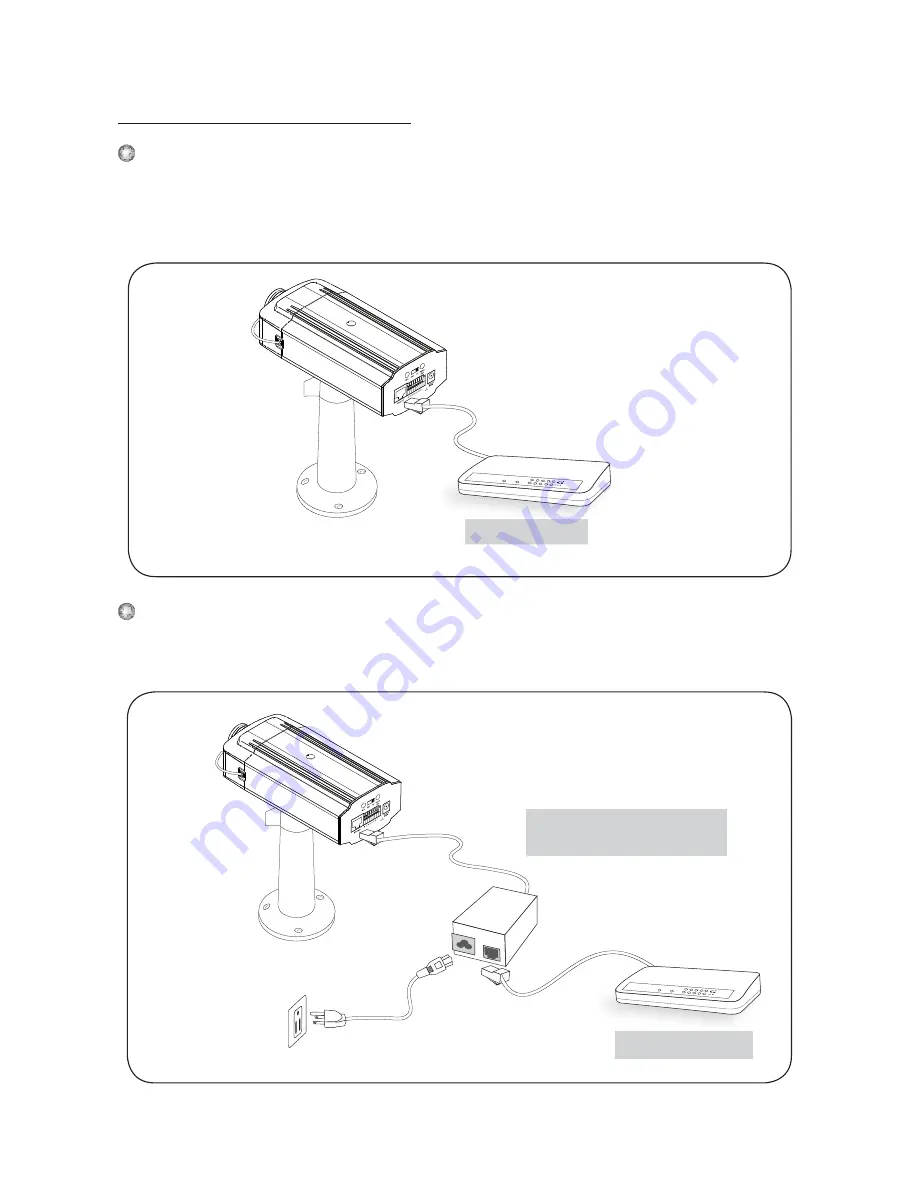
When using a PoE-enabled switch

The camera is PoE-compliant, allowing transmission of power and data via single 

Ethernet cable. See the following illustration to connect the camera to a PoE-

enabled switch via Ethernet cable.

PoE switch

PoE switch

POWER

COLLISION

LINK

RECEIVE

PARTITION

1

2

3

4

5

Summary of Contents for IP7251

Page 1: ......

Page 2: ...anual for the operating temperature Power off the Network Camera as soon as it is found smoking or smelt unusual Do not place the Network Camera around the heat sources such as television or oven Keep the Network Camera away from direct sunlight Do not place the Network Camera in high humid environments Contact your distributor when such cases happen Warning Before Install ...

Page 3: ... Network Camera on unsteady surfaces Do not touch the Network Camera when it s lightening Do not disassemble the Network Camera Do not drop the Network Camera Do not insert any object into the Network Camera such as needles ...

Page 4: ...EN 3 English Camera stand CS mount lens IP7251 Warranty card Power adapter Quick installation guide Software CD 1 Package Contents L type hex key wrench C mount ring for C mount lens ...

Page 5: ...10 100 RJ45 socket Indented reset button General I O terminal block Audio out MIC in External Internal MIC switch Front panel Back panel Lens Focus controller Zoom controller 2 Physical Description Built in MIC Light sensor Status LED ...

Page 6: ... lens counterclockwise slowly until it gets the best attitude 2 Connect the lens cable plug to the camera connector 3 Mounting the Lens to the Camera 1 2 General Connection without PoE 1 Connect the camera to a switch via Ethernet cable 2 Connect the supplied power cable from the camera to a power outlet POWE R COLLIS ION LINK R E CE IVE PAR TITION 1 2 3 4 5 1 2 4 Network Deployment Ethernet switc...

Page 7: ... CE IVE PAR TITION 1 2 3 4 5 non PoE switch PoE power injector optional When using a PoE enabled switch The camera is PoE compliant allowing transmission of power and data via single Ethernet cable See the following illustration to connect the camera to a PoE enabled switch via Ethernet cable PoE switch PoE switch POWE R COLLIS ION LINK R E CE IVE PAR TITION 1 2 3 4 5 ...

Page 8: ...nstallation Wizard 2 IW2 5 Assigning IP Address 1 Install the Installation Wizard 2 under the Software Utility directory from software CD 2 The program will conduct analyses on your network environment After your network is analyzed please click on the Next button to continue the program 3 The program will search the VIVOTEK Video Receivers Video Servers or Network Cameras on the same LAN 4 After ...

Page 9: ... the Network Camera from the Internet 2 Retrieve live video through web browsers or recording software 3 Unscrew the zoom controller to adjust the zoom factor Upon completion tighten the zoom controller 4 Unscrew the focus controller to adjust the focus range Upon completion tighten the focus controller W N T 3 4 ...

Page 10: ...pe hex key wrench to loosen the lens mounting screw the CS mount ring becomes rotatable 4 Use a coin to turn the CS mount ring fine tune the distance between the sensor and the lens 5 When finished tighten the lens mounting screw to fix the CS mount ring 6 Attach the CS mount lens back to the camera body Lens mounting screw CS mount ring 1 2 3 4 ...

Page 11: ...P N 625006300G Ver 1 0 Copyright 2008 VIVOTEK INC All rights reserved c ...

Reviews: