background image

EN-5

English

Network Deployment

4

POWER

COLLISION

LINK

RECEIVE

PARTITION

1

2

3

4

5

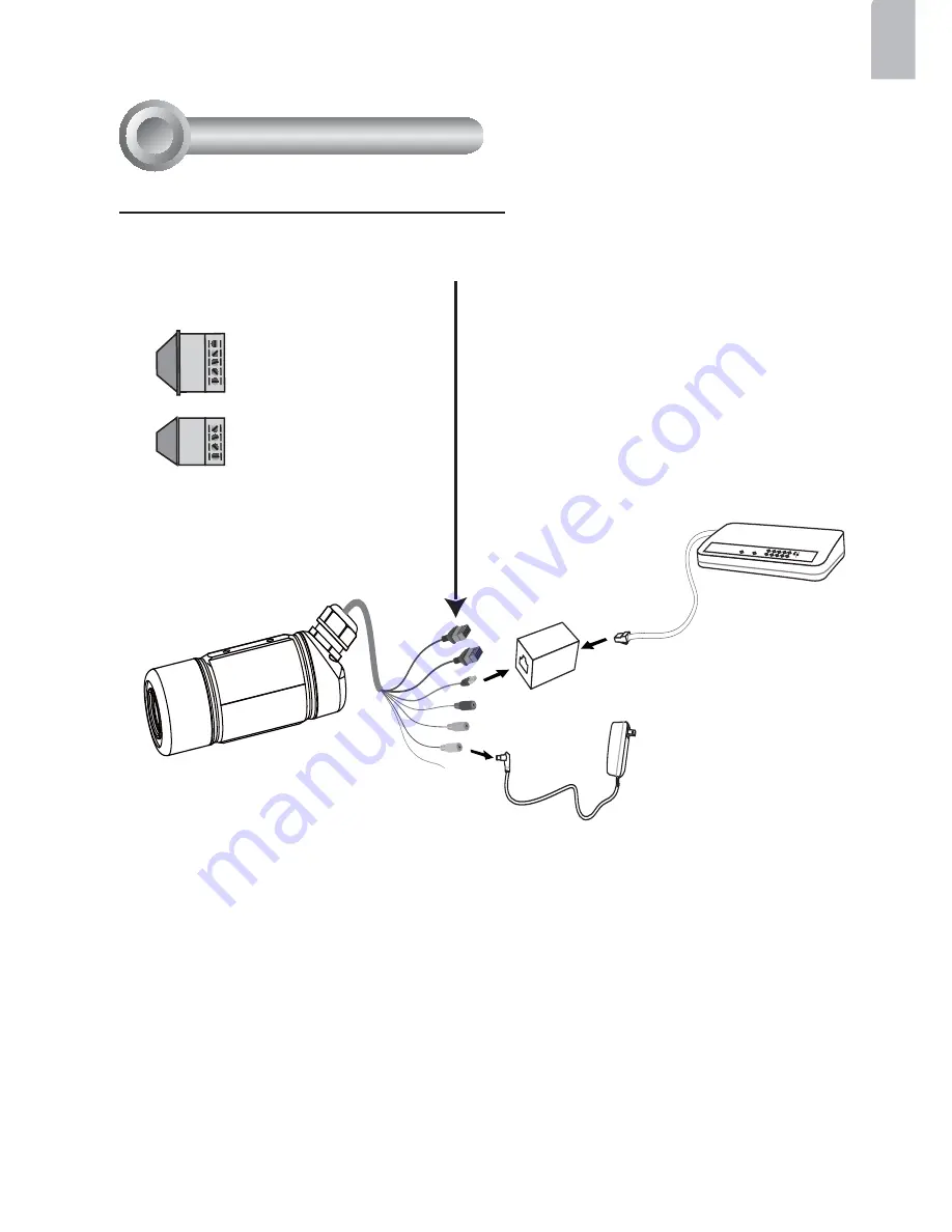
1. If you have external devices such as 

sensors and alarms, connect them to the 
general I/O terminal block.

2. Use the supplied RJ45 female/female 

coupler to connect the Network Camera 
to a switch.

    Use Category 5 Cross Cable when 

Network Camera is directly connected to 
PC.

3. Connect the power cable from the 

Network Camera to a power outlet. 

N.C.

485B

485A

AC24V

AC24V

N . C . :   No  Connector
4 8 5 B :  RS485-
4 8 5 A :  RS485+
AC24V: Power in AC 24V

G N D :  Ground
D I   :  Digital Input
D O  :  Digital Output
+ 1 2 V   :  Power, 12V DC

GND
DI
DO
+12V

General Connection (without PoE)

Summary of Contents for IP7142

Page 1: ......

Page 2: ... manual for the operating temperature Power off the Network Camera as soon as smoke or unusual odors are detected Do not touch the Network Camera during a lightning storm Do not place the Network Camera on unsteady surfaces Do not drop the Network Camera Do not insert sharp or tiny objects into the Network Camera ...

Page 3: ...EN 2 Package Contents 1 Software CD IP7142 Screws RJ45 Female Female Coupler Warranty Card Spanner Quick Installation Guide Camera Stand Sun Shield Power Adapter Silica Gel ...

Page 4: ... Physical Description 2 Connectors Ethernet 10 100 RJ45 Plug Audio Out green Microphone In pink Power Cord Socket black General I O Terminal Block Ground Front Panel IR LED Lens Reset Button Status LED Light Sensor ...

Page 5: ...EN 4 Hardware Installation 3 1 Open the lens cover 2 Secure the Network Camera to the wall ceiling by the supplied camera stand 1 2 3 ...

Page 6: ...female coupler to connect the Network Camera to a switch Use Category 5 Cross Cable when Network Camera is directly connected to PC 3 Connect the power cable from the Network Camera to a power outlet N C 485B 485A AC24V AC24V N C No Connector 4 8 5 B RS485 4 8 5 A RS485 AC24V Power in AC 24V AC24V Power in AC 24V G N D Ground D I Digital Input D O Digital Output 12V Power 12V DC GND DI DO 12V Gene...

Page 7: ...switch The Network Camera is PoE compliant allowing transmission of power and data via avsingle Ethernet cable Follow the below illustration to connect the Network Camera to a PoE enabled switch via Ethernet cable POWE R COLLIS ION LINK R E CE IVE PAR TITION 1 2 3 4 5 Non PoE Switch PoE Power Injector optional POWE R COLLIS ION LINK R E CE IVE PAR TITION 1 2 3 4 5 PoE Switch ...

Page 8: ...ideo Receivers Video Servers and Network Cameras on the same LAN 4 After searching the main installer window will pop up Click on the MAC that matches the one labeled on the side of the camera lens or S N number on the label of carton to connect the Internet Explorer to the Network Camera 0002D17151CD 1 2 Model No IP7142 P N 100043690G F W Ver 0100G CARTON OF NO 01 MADE IN TAIWAN 0 Q ty 1 PCS EAN ...

Page 9: ...work Camera from the Internet 2 Retrieve live video through web browsers or recording software 3 Unscrew the zoom controller to adjust the zoom factor Upon completion tighten the zoom controller 4 Unscrew the focus controller to adjust the focus range Upon completion tighten the focus controller T W N W N T ...

Page 10: ...e If you want to use the supplied sun shield for outdoor environments please follow the steps below to install 1 Tighten the supplied two screws 2 Attach the supplied sun shield to the Network Camera and slide it to the desired position 3 Fix the sun shield with the supplied two screws Please use different screws for ceiling mount 4 Secure the Network Camera to the wall ceiling by the supplied cam...

Page 11: ......

Reviews: