background image

DU6693Z DLP Projector - User Manual 


21 

UM66931217EN00


Adjusting the Projection Mode 

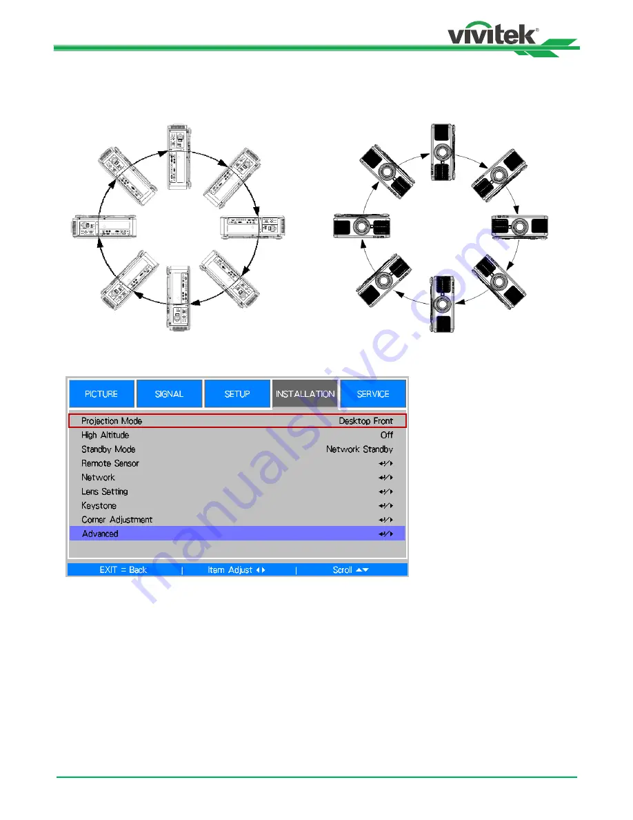
DU6693Z is designed for set up in all angles including desktop, ceiling, portrait and free-tilt installation as shown in the 
below illustration. 


You can change the direction of the image using the Projection Mode. The projector has a smart cooling mechanism, 
which regulate the fan automatically according to the projection mode. 

 
Use the 

 or 

 buttons to select a projection mode to change the direction of the image. The selectable options are as 

follow: 

Auto-Front: 

Turn on the orientation sensor to change automatically the direction of the image. 

Desktop Front:

 Install the projector on the desktop and project the image forward. 

Desktop Rear:

 Install the projector on the desktop and project the image from the rear of the screen. 

Ceiling Front:

 Mount the projector on the ceiling and project the image forward. 

Ceiling Rear: 

Mount the projector on the ceiling and project the image from the rear of the screen. 


Summary of Contents for DU6693Z

Page 1: ...DU6693Z User s Manual User s Manual ...

Page 2: ...y 19 Turning On the Projector 19 Turning Off the Projector 20 Adjusting the Projection Mode 21 Adjusting the Projected Image Position 22 Adjusting the Focus and Zoom 22 Preventing the Unauthorized Use of the Projector 23 Using the Control Panel Lock 23 Using the Security Lock 24 Using Control ID for Multi Projector Application 25 Using the Constant Brightness Function to Maintain the Brightness Ou...

Page 3: ...6693Z DLP Projector User Manual UM66931217EN00 2 Configurations of Terminals 54 DU6693Z Lens Series 55 Product Dimensions 56 LED Indication 57 Common Problems and Solutions 58 About the Vivitek Support 60 ...

Page 4: ...cturer does not provide any statement or warranty of the contents in the manual and clearly give up the implied warranties of merchantability and of fitness for a particular purpose The manufacturer reserves the rights to modify the publication and change the contents of the materials at any time without notice to any person About the Manual The manual describes how to install and use the projecto...

Page 5: ...r to a little lead a chemical known to the Stage of California resulting in risks of barrenness Please remember to wash hands after handling NOTIFICATION CANADA This Class A digital equipment complies with Canadian ICES 003 CE NOTIFICATION This is a Class A product which complies with rules for CE marking This product may cause radio interference that the user may be supposed to take adequate meas...

Page 6: ...cedures of operation LASER LIGHT AVOID DIRECT EYE EXPOSURE Do not point laser or allow reflected laser light toward other people or reflective objects Direct or scattered light can be hazardous to eyes and skin There is a potential hazard of eye exposure to laser radiation if the included instructions are not followed Caution use of controls adjustments or performance of procedures other than thos...

Page 7: ...and then stabilize getting into standby mode User should only use the connectors or accessories provided by the manufacturer 12 When user turns on the projector the red LED indicator would flash until stabilize Do not look at the lens directly while the projector is running 13 Unplug the power cord of the equipment if there is a thunderstorm or the equipment is not going to be used for a long time...

Page 8: ...inting The contents may be frequently updated due to the continuous product improvement and customer feedback You can find the latest version of the Manual and the manual of other Vivitek products on www vivitekcorp com Packing Checklist The following items are included in the packaging box of the DU6693Z series projector If any loss or damage to any item contact your dealer or Vivitek customer se...

Page 9: ... Rear IR Receiver The Receiver for IR signals from the remote control Rear right View 9 I O Connector Panel Connect to various input control or output terminals to the projector 10 Kensington Lock Attach the projector to a permanent object with the Kensington slot and a security cable 11 Slide Switch Switch it to corresponding input voltage 12 AC Power Switch Turn on off the AC power of the projec...

Page 10: ...verloading may damage the projector or cause injury 17 Recess for projector handling These four recesses can be used for handling the projector 18 Ceiling Mounting Hole Total six M4 screw holes with maximum depth 14mm 19 Security Slot The slot can be used for Short term protection Note When installing ensure that you use only UL Listed ceiling mounts Contact your dealer for information on mounting...

Page 11: ...signal transmitter WIRED REMOTE Connect the supplied remote controller to the projector HDBaseT LAN Connect an Ethernet cable Cat5 Cat6 not supplied from a computer network device or HDBaseT transmitter HDMI Connect the HDMI cable from a computer or video device DVI D Connect to DVI D cable from a DVI D output of the device DisplayPort Connect the DisplayPort cable from a computer or video device ...

Page 12: ...tion ENTER Use the button to select settings or confirm the changed settings EXIT Push the button to return to the menu on the previous level or exit the OSD menu CENTER LENS Push the button to center the lens and calibrate the parameter of lens shift focusing and zooming Note The lens memory function requires the accurate lens adjustment parameter Please center the lens every time after the lens ...

Page 13: ...t the OSD Menu AUTO PC You can use this function to execute signal source auto synchronization BLANK Press the button to temporarily interrupt the projection STATUS Show OSD MENU SERVICE VGA Select VGA input source COMPONENT Select Component input source ASPECT Press the button to display aspect ratio options HDMI1 Select HDMI input source HDMI2 Not available for this model DVI Select DVI D input ...

Page 14: ...mission to control the projector It is not necessary to point the remote directly at the projector Provided you are not holding the remote perpendicular to the sides or the rear of the projector the remote will function well within a radius of about 10 meters 25 feet and 15 degrees above or below the projector level If the projector does not respond to the remote control move a little closer ...

Page 15: ...ghting turned on Certain high frequency fluorescent lights can disrupt remote control operation Be sure nothing obstructs the path between the remote control and the projector Do not expose the remote control to high temperature or humidity otherwise the remote control will not work functionally Battery installation instructions Make sure the battery is installed with the correct polarity Do not u...

Page 16: ...ler for information about mounting the projector on a ceiling Only use the projector on a solid level surface serious injury and damage can occur if the projector is dropped Caution Ensure that the hot air from the exhaust vent is not sucked into the projector Ensure the air intake and exhaust vents are unobstructed and keep the required distance from any object Below is required minimum distance ...

Page 17: ...DU6693Z DLP Projector User Manual 16 UM66931217EN00 Mounting the Projector For mounting the projector please use UL Listed ceiling mounts and M4 screws maximum depth of screw 14 mm ...

Page 18: ...oving or installing the lens Keep fingerprints dust or oil off the lens surface Do not scratch the lens surface Work on a level surface with a soft cloth under it to avoid scratching If you remove and store the lens attach the lens cap to the projector to keep off dust and dirt Install New Lens 1 If the Lens cover is installed pull the edge of the lens cover with one hand so that the lens cover ca...

Page 19: ...tor be sure to remove the lens cap from the back of the optional lens before installing the optional lens into the projector Failure to do so will cause damage to the projector and lens There is one safety switch inside the lens slot on the projector to prevent unexpected injury by laser beam the projector cannot be turned on if the projection lens has not been installed or is not installed correc...

Page 20: ...important that the projector is powered on correctly in order to avoid damage to components and un necessary wear and tear Refer to the following guide to power on the projector 1 Press the main power switch to the on I position as shown POWER LEDs flashes then lights red 2 Press the POWER button on the control panel or ON button on the remote control 3 The Power LED and LIGHT LED flashes green ti...

Page 21: ...er strip equipped with a switch and a breaker Do not turn off the AC power supply within 10 seconds after making adjustment or changing the setting Doing so is possible to cause loss of adjustments and settings and return to default Refer to the following guide to shut down the projector 1 Press the POWER button on the control panel or OFF button on the remote control once the Power Off window dis...

Page 22: ...e projection mode Use the or buttons to select a projection mode to change the direction of the image The selectable options are as follow Auto Front Turn on the orientation sensor to change automatically the direction of the image Desktop Front Install the projector on the desktop and project the image forward Desktop Rear Install the projector on the desktop and project the image from the rear o...

Page 23: ... Note The projector is equipped with safety switch inside the lens mount hole the projection lens must be installed in the projector before turning on the power Or the projection can t be started There is a Lens Lock function on OSD menu to disable lens control adjustment for avoiding possible misoperation after you finish the adjustment please make sure to disable the lock before performing the l...

Page 24: ... Control Panel Lock to enable the function as below illustration Once Control Panel Lock is enabled all of control buttons on the projector are locked Below message is shown on the screen few seconds if any control buttons is pressed Unlocking the Control Panel Once Control Panel Lock is enabled all of control buttons on the projector are disabled Please enter the OSD option SETUP Advanced Control...

Page 25: ...urned on the pop up message for setting up the password Lock as is shown as below Press arrow buttons to set up your password the password can be the combination of four arrow keys Control Panel Lock is turned on the pop up message will be shown Lock as below select OK to confirm or Cancel to ignore the setting When you turn on the projector next time the pop up window will remind you to input the...

Page 26: ...ntrol ID Number option then press Enter buttons use button to increase the number or button to decrease the number This option is available when Projector ID Control is turned on Set the identification number of remote control Press and hold ID SET button on the remote control around 5 seconds Power led indicator is flashing red periodically Press two digits to set desired ID number each pressing ...

Page 27: ...or and remote control The identification number of the projector and remote control can be checked by SERVICE menu as below figure X represents that the function is not enabled the number 26 is the current identification number of the remote control Note Project ID Control function is available when the option is turned on and remote control wire is not plugged into the wire remote jack If ID Cont...

Page 28: ... to increase the light output to your pre defined brightness level and thus maintaining a constant level of brightness To use this function follow the steps below 1 Select CONTROL Light Power Laser Mode Change it to Custom Power Level with a value under 100 For example 90 or 85 The reduced power percentage will be used to later regulate the brightness when the Constant Brightness function is enabl...

Page 29: ...n the nut on the joint and connect the signal source equipment to the projector according to the figure below Connecting a Computer You can connect the PC signal to be projected to the projector through the DVI D HDMI DisplayPort VGA or RGBHV BNC cable If the signal to be input is VGA signal connect the VGA cable to the external display to simultaneously monitor the projected content Connecting a ...

Page 30: ...he projector cannot receive the IR signal from the remote control due to the overly long distance or obstacles you can connect the cable to the IR remote control or the external IR transmitter optional via the WIRE input port to expand the working range of the remote control 3D Sync Out In Connect to 3D IR sync signal transmitter or device Caution When the terminal of the remote control cable is i...

Page 31: ...c projection screen and other 12V trigger device you can connect these devices to the 12V trigger to output and configure the output 12V signal settings The projector will output 12V signals when it s turned on You can use the signal to control the screen or device by turning on the OSD option under SETUP Trigger 1 or Triger 2 ...

Page 32: ...projector supports the video signal R 232 IR remote control and the reception of the network control signals but do not support Power over Ethernet PoE The baud rate will be switched to 9600 automatically If RS232 command is sent via external HDBaseT transmitter If the command is sent via the HDBaseT transmitter the longest transmission distance is 100 meters The projection may be interrupted or i...

Page 33: ...l buttons on the projector to navigate and make changes to the OSD The following illustration shows the corresponding buttons on the remote control and on the projector 1 To open the OSD press the Menu button on the OSD control panel or remote control There are five folders on the menu Press the cursor or buttons to move through secondary menus 2 Press or to select menu items and or to change valu...

Page 34: ...Gamma 1 0 1 8 2 0 2 2 2 35 2 5 S Curve DICOM Advance Input Balance Red Offset Green Offset Blue Offset Red Gain Green Gain Blue Gain HSG Red Hue Saturation Gain Green Hue Saturation Gain Blue Hue Saturation Gain Cyan Hue Saturation Gain Magenta Hue Saturation Gain Yellow Hue Saturation Gain White Hue Saturation Gain Reset Signal Input Selection HDMI I DisplayPortDVI D VGA Component BNC HDBaseT EDI...

Page 35: ...VGA Setup H Total H Start V Phase V Start Auto Sync Execute Setup Language English Français Español Deutsch Português 简体中文 繁體中文 日本語 한국어 Light Power Laser Mode Custom Power Level Constant Brightness Normal Eco Custom Power Level Off On Startup Logo On Off Digital Alignment Digital Zoom Digital Pan Digital Scan Reset Trigger 1 On Off Trigger 2 On Off Dynamic Black On Off 3D 3D Format Off Auto Side b...

Page 36: ...jection Mode Auto Front Desktop Front Desktop Rear Ceiling Front Ceiling Rear High Altitude Sea Level A1 4000ft 1219m A2 8000ft 2438m Standby Mode Network Standby Eco Remote Sensor Front Rear Front Rear HDBaseT Off Network IP Address Subnet Mask Gateway DNS DHCP Apply On Off Mac Address Lens Setting Lens Lock Off On Lens Control Zoom Focus Lens Shift Shift V Shift H Lens Type Non UST Lens UST Lens...

Page 37: ...aseT Auto Power Off Auto Power On Message Box Screen Format 16 10 16 9 4 3 H V Alignment H Zoom V Zoom H Shift V Shift Reset SERVICE Model Serial Number Software Version Control Remote ID X X Source Information Active Source Pixel Clock Signal Format H V Refresh Rate Sync Type Sync Polarity Scan Type Usage Time Laser Time Power On Time Factory Reset ...

Page 38: ...on level of the color the higher the level the higher the saturation Hue Use or buttons to adjust the level of hue for reproduction of the true color Main Color Hue R Magenta Yellow G Yellow Cyan B Cyan Magenta C Green Blue M Blue Red Y Red Green Sharpness Use or buttons to adjust the sharpness The purpose of this adjustment is to change the value of the high frequency detail Noise Reduction Use o...

Page 39: ...ne Red Green and Blue color Offset These three options will shift the color spectrum for the whole image and change its brightness if minimal amount of red green or blue appears in the gray areas you can adjust the offset of the corresponding color accordingly By increasing the offset the image brightness will become lower Gain These three options are used to increase or decrease the range of colo...

Page 40: ...Select the input source from the VGA Component BNC Select the Input source from the BNC The input source can be RGBHV or Component signal from computer or component video enabled device HDBaseT Select the input source from the HDBaseT EDID Mode Sometimes the projector may not display the desired timing due to the compatibility of the device you can use this function to select the desired timing fo...

Page 41: ...or space and set the black to 16 16 and 16 RGB while set the white to 235 235 235 if an 8 bit image is used to correspond to the luminance value defined in the digital component standard Aspect Ratio This function allows the user to adjust the aspect ratio of the image Overscan Noise may appear on the edge of the projected image use this function to select Crop to hide the edge of the image or Off...

Page 42: ... between 100 and 35 Note this function is enabled only when Laser Mode is set to the Custom Power Level Constant Brightness Select On to enable this function A built in light sensor inside the projector monitors the level of light so that when a reduction in light is detected the sensor will regulate dynamically the electricity power to increase the light output to your pre defined brightness leve...

Page 43: ...l is HDMI 1 4 3D The HDMI 1 4 3D signal connects to the projector through HDBaseT transmitter Side by Side Manually switch the 3D Format to Side by Side This option is only applicable to the HDMI input signal or the signal through a HDBaseT transmitter Top Bottom Manually switch the 3D Format to Top Bottom This option is only applicable to the HDMI input signal or the aforementioned signal sent th...

Page 44: ... to Off to unlock the control panel Security Lock The projector has a built in security feature to lock the OSD control panels and deny remote control operation for preventing the unauthorized use of the Projector To lock the projector please select the option to On and define a password followed the popup window ID Control Enable This option allows you to enable the projector ID control function ...

Page 45: ...000ft 1219m to 8000ft 2438m A2 8000ft 2438m When using the projector above 8000ft 2438m Standby Mode Use the or buttons to set up Standby Mode Network Standby The projector maintains in the standby status at higher power 3W for network control In this mode the projector can be turned on via network control system Eco The projector maintains in the standby status at the lowest power 0 5W the projec...

Page 46: ...NS Set the DNS the input method is same as the IP address DHCP Set DHCP to ON OFF When DHCP is set to ON the DHCP server of the domain will assign an IP address to the projector The IP address will appear in the IP address window and you don t need to make any input Otherwise the domain does not or cannot assign any IP address and 0 0 0 0 is shown on the IP address window Apply Select this button ...

Page 47: ...tor otherwise please set it to Non UST Lens There are two default positions one is for regular zoom or fixed focus lens Non UST the reference position is 0 of image width in horizontal shift and 0 of the image height in vertical shift anther one is for Ultra Short Throw Lens UST the default position is around 0 of image width in horizontal shift and 56 of image height in vertical shift When perfor...

Page 48: ...tor will adjust the Lens position Zoom and Focus automatically Save Memory Use or to select the memory set for storing the setting then press ENTER button to confirm Clear Memory Select the memory set to be cleared then press ENTER button to confirm clearing memory set Keystone When the image is projected toward the screen at angle the image becomes distorted trapezoid this function can be used to...

Page 49: ... of the remote control to turn on the projector Set this function to OFF if it s unnecessary Message Box This function allows you to disable the pop up message at bottom right of the screen or any reminding message Set this option off to disable the message on the screen except of OSD menu Screen Format This function allow you to resize the projected image for fitting the projection screen the sel...

Page 50: ... version in the projector Control Remote ID Display current projector ID and remote control ID Source Information Display the current input source information Usage Time Display current projector time of the projector Laser Time Display current lamp usage Power On Time Display the total Power On time of the projector Factory Reset The user can use this function to reset all the settings to factory...

Page 51: ...t 5 BNC VGA In RS 232 VGA Out 3D Sync In Out 12v Trigger1 2 Wired Remote HDBaseT LAN Shared Service Port Projection Method Table Top Ceiling Mount Front or Rear Free tilt Portrait Security Solutions Kensington Security Slot Security Bar Anti Theft Lens Screw Dimensions WxDxH 500 x 580 x 205mm 19 7 x 22 8 x 8 1 Weight 27kg 59 5lbs Available Colours White DU6693Z WH Black DU6693Z BK Noise Level 32dB...

Page 52: ...4 89 102 25 O O O 1280 x 768 68 63 84 84 117 50 O O O 1280 x 800 49 70 60 00 83 50 O O O 1280 x 800 62 80 74 93 106 50 O O O 1280 x 960 60 00 60 00 108 00 O O O 1280 x 960 85 94 85 00 148 50 O O O 1280x1024 63 98 60 02 108 00 O O O 1280x1024 79 98 75 02 135 00 O O O 1280x1024 91 15 85 02 157 50 O O O 1366 x 768 47 71 60 00 85 50 O O O 1400X1050 65 32 60 00 121 75 O O O 1400X1050 82 28 74 87 156 00...

Page 53: ...27 00 O O O O O O O 576p 31 25 50 00 27 00 O O O O O O O HDTV 1035i 33 75 60 00 74 25 O O O O O O O 1080i 28 13 50 00 74 25 O O O O O O O 1080i 33 72 59 94 74 18 O O O O O O O 1080i 33 75 60 00 74 25 O O O O O O O 720p 37 50 50 00 74 25 O O O O O O O 720p 44 96 59 94 74 18 O O O O O O O 720p 45 00 60 00 74 25 O O O O O O O 1080p 26 97 23 98 74 18 O O O O O O O 1080p 27 00 24 00 74 25 O O O O O O O...

Page 54: ...920x1080 50 00 1125 56 25 O 1080i59 Side by Side Half 1920x1080 59 94 1125 67 43 O 1080i60 Side by Side Half 1920x1080 60 00 1125 67 50 O 1080p50 Side by Side Half 1920x1080 50 00 1125 56 25 O 1080p59 Side by Side Half 1920x1080 59 94 1125 67 43 O 1080p60 Side by Side Half 1920x1080 60 00 1125 67 50 O 1080p50 Top and Bottom 1920x1080 50 00 1125 56 25 O 1080p59 Top and Bottom 1920x1080 59 94 1125 6...

Page 55: ...een Input 10 GND 3 Blue Input 11 GND 4 N C 12 VGA_SDA 5 N C 13 H Sync 6 GND 14 V Sync 7 GND 15 VGA_SCL 8 GND 16 GND HDMI 19 pin Type A 1 T M D S Data 2 Input 11 Ground 2 Ground 12 T M D S Clock C Input 3 T M D S Data 2 Input 13 CEC 4 T M D S Data 1 Input 14 N C 5 Ground 15 SCL 6 T M D S Data 1 Input 16 SDA 7 T M D S Data 0 Input 17 Ground 8 Ground 18 P5V 9 T M D S Data 0 Input 19 HPD 10 T M D S Cl...

Page 56: ...e Fix 1 85 11 6mm 40 500 0 76 1 D88 WZ01 Wide Zoom 1 85 2 5 18 7 26 5mm 1 41 1 40 500 1 25 1 79 1 D88 ST001 Standard Lens 1 7 1 9 26 34mm 1 3 1 40 500 1 73 2 27 1 D88 SMLZ01 Semi Long Zoom 1 86 2 48 32 9 54 2mm 1 65 1 40 500 2 22 3 67 1 D88 LOZ101 Long Zoom 1 1 85 2 41 52 8 79 1mm 1 5 1 40 500 3 58 5 38 1 D88 LOZ201 Long Zoom 2 1 85 2 48 78 5 121 9mm 1 55 1 40 500 5 31 8 26 1 The best performance ...

Page 57: ...DU6693Z DLP Projector User Manual 56 UM66931217EN00 Product Dimensions ...

Page 58: ...s opened Check if the top cabinet is installed properly Red Cycles of 4 Cooling fan error Contact with your nearest authorized dealer or service center On Red System Error Contact with your nearest authorized dealer or service center Light Source LED LED Display Projector status Procedure Off Light source is off Flashing Green Projector is turning on Red Cycles of 6 Light source lit fail Contact w...

Page 59: ...n 1 Verify the settings on your notebook or desktop PC 2 Turn off all equipment and power up again in the correct order 3 Check if shutter is enabled Problem The image is blurred 1 Adjust the Focus on the projector 3 Performance Auto Sync on the remote control or projector 4 Ensure the projection distance is within the specified range 5 Check that if the projection lens is clean Problem The image ...

Page 60: ...eck if the lens is installed properly improper lens installation may cause to lens cannot work normally Please follow the lens installation procedure to check again 2 Check if Lens Lock function is enabled locking the lens will disable all of lens adjustment functions 3 Perform Center Lens function to calibrate the Lens again 4 Replace the other lens to check the problem if the lens is available 5...

Page 61: ...Email support vivitek eu URL http www vivitek eu support tech support North America Vivitek Service Center 15700 Don Julian Road Suite B City of Industry CA 91745 U S A Tel 855 885 2378 Toll Free Email T services1 vivitekcorp com URL www vivitekusa com Asia and Taiwan Vivitek Service Center 5F No 186 Ruey Kuang Road Neihu District Taipei Taiwan 11491 Tel 886 2 8797 2088 ext 6899 Direct Tel 0800 04...

Reviews: