


D-304493 TOWER CAM PG2
Installation Instructions
5
2.3. Enrollment
Refer to the PowerMaster control panel's Installer Guide and follow the procedure under the
"02:ZONES/DEVICES"
option of the Installer Menu.
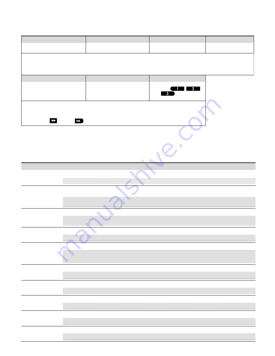
A general description of the procedure is provided in the following flow chart.
Step 1
Step 2
Step 3
Step 4
Enter the Installer menu and select
“
02:ZONES/DEVICES
”
Select "ADD NEW DEVICE"
See Note 1
Enroll the device (see Figure 5) or
enter the device ID
Select a detector number for
the new detector
02:ZONES/DEVICES
ADD NEW DEVICES
ENROLL NOW or
ENTR ID:XXX-XXXX
Z09:Motion Camra
ID No. 142-XXXX
MODIFY DEVICES
Step 5
Step 6
Step 7
Configure Location, Zone Type &
Chime parameters
Enter PARTITIONS.
See Note 2
Assign partitions to the detector by
pressing the
,
and/or
buttons on the
panel
Z09.LOCATION
Z09.ZONE TYPE
Z09.SET CHIME
Z09/PARTITIONS
Z09:P1
P2 P3
means scroll
and select
Notes:
[1] If the detector is already enrolled you can configure the detector parameters and assign partitions via the
“Modify Devices”
option – see
Step 2.
[2] PARTITIONS will appear only if PARTITIONING was previously enabled in a panel that supports the Partitioning feature (for further details,
see "Partitioning" in the PowerMaster Installer Guide).
2.4. Configuring the Detector Parameters
Enter the
DEVICE SETTINGS
menu and follow the configuration instructions for the TOWER CAM PG2 PIR detector as described below.
Option
Configuration Instructions
ALARM LED
Define whether or not to activate the alarm LED indication.
Optional settings: ON (default) and OFF.
PIR SENSITIVITY
Define if the detector operates at regular or high PIR sensitivity, or that at least one detection zone must be crossed
before an alarm is triggered (One Region).
Optional settings: LOW (default), HIGH and One Region.
Note:
For EN and UL compliance, the detector should be set to "One Region".
DISARM ACTIVITY
Define whether or not to set the activity time during Disarm mode.
Optional settings: NOT Active (default), YES – no delay, YES + 5s delay, YES + 15s delay, YES + 30s delay, YES +
1m delay, YES + 2m delay, YES + 5m delay, YES + 10m delay, YES + 20m delay and YES + 60m delay.
OUTDOOR ANTI-M
Enable or disable the outdoor anti-masking feature.
Optional settings: Disabled (default) and Enabled.
ALARM Hours
Define whether motion alarms are always enabled or only when dark (at night).
Optional settings: Day and Night
(default) and Night only.
Note:
For UL/ULC installation, the Alarm Hours feature when enabled for night protection should only be used as
supplemental protection to the protection covering the protected area.
IMAGE COLOR
Define whether the image will be in black & white or color.
Optional settings: Black & White (default) and Color.
IMAGE RESOLUTION
Set the pixel quality of the image. Select 160 x 120 for lower quality or 320 x 240 for higher quality.
Optional settings: 320 x 240 (default) and 160 x 120.
IMAGE QUALITY
Set the quality of the image.
Optional settings: High (default) and normal.
IMAGE BRIGHTNESS
Set the brightness of the image.
Optional settings: Normal (default) -3, -2, -1, +1, +2 and +3.
IMAGE CONTRAST
Set the contrast of the image.
Optional settings: Normal (default) -3, -2, -1, +1, +2 and +3.


