


Managing System Configuration
48
The Management tab includes the following:
•
PowerLink2 ID –
Allows you to connect to the PowerLink2 with the ID instead
of serial number.
•
Ports
- Allows changing the network ports in which PowerLink2 operates.
HTTP is the port used for accessing your PowerLink2 from the internal
network. HTTPS is used for access from the internet. If PowerLink2 is
connected to a router that supports UPNP, checking the Open using UPNP will
open the ports on the router automatically.
•
Session Timeout
– The amount of minutes until the user will be auto logged out
from the web interface. Setting this to 0 (zero) will disable auto logout.
•
Factory Settings
– Press the RESET button to restore the PowerLink2 to it's
factory defaults
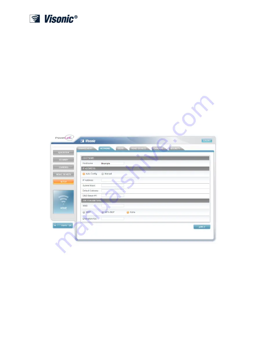
Network
The Network tab includes the following:
•
Hostname
– The hostname that PowerLink2 will report to the network
•
IP Address
– The network parameters of the PowerLink2:
•
IP Address –
The IP address of the Visonic PowerLink2
•
Subnet Mask
– The subnet mask used with the IP Address
•
Default Gateway
– The default gateway of the network
•
DNS Server
– The IP address of the DNS server


