4
D-301436
SYSTEM SETUP
To set up your system, follow the steps below. After
you complete steps 1 through 5, your system's Base
Unit will automatically call the Monitoring Center to
guide you through the rest of the set up.
Step 1
Select Base Unit Location
If possible, select a central location in your home for
the Base Unit. This location should be in the area
where you spend most of your time. The location
should also enable an optimal signal reception range
of 150 ft. for pendants and smoke detectors.
The Base Unit can be placed on a table, desk, or
counter. It also can be mounted on a wall.
Make sure that the location you have selected is near
an electrical outlet and a phone jack.
Note:
Certain remote areas of your residence may lie
outside the reception range of the base unit, resulting
in the unit not being able to receive transmissions
directly. In this case, a Repeater (MCX-600) can be
used to increase the base unit reception range.
Contact a Visonic representative for further details.
Step 2
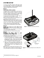
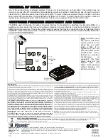
Rotate the Antenna on the Base Unit
(Figure 3)
The antenna helps your pendant(s) and detector(s)
communicate with your Base Unit.
Rotate the antenna to its utmost vertical position.
Step 3
Connect the Base Unit to your
Telephone Line (Figure 4)
∗
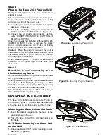
The Base Unit communicates with your Monitoring
Center through your telephone line.
1.
Locate the phone jack on your wall where you want
to connect your Base Unit. If a phone is already
plugged into that jack, unplug it and connect it to
the "PHONE" connector on the back of the Base
Unit. Your telephone will still function normally.
2.
There is a phone cord already connected to the
"Wall Jack" on your Base Unit. Plug the other end
of that phone cord into the phone jack on your
wall. The Base Unit is now connected to your
telephone line.
Note:
Be aware of other phone line services such as
DSL. If DSL service is present on the phone line, you
must install a filter. See Figure 4 for proper installation.
Figure 3
– Base Unit with Raised Antenna
For locations with
DSL service.
DSL
FILTER
Figure 4
– Connecting Telephone Line to Base Unit
∗
For advanced phone connections see page 12.


