3
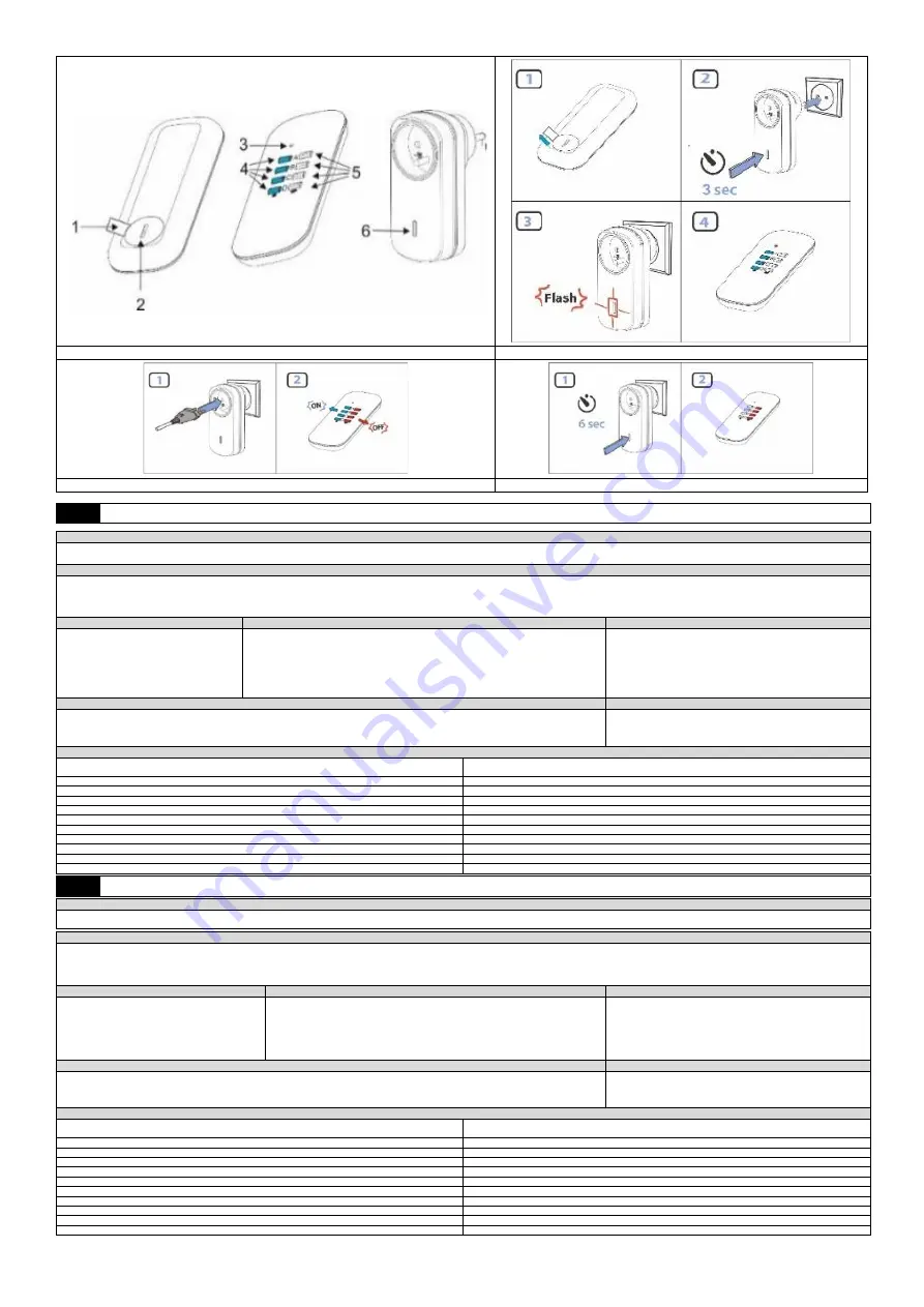
Fig. 1/rys.1/Abb.1/ Fig.1/Pис. 1
Fig. 2/rys.2/Abb.2/ Fig.2/Pис. 2
Fig. 3/rys.3/Abb.3/ Fig.3/Pис. 3
Fig. 4/rys.4/Abb.4/ Fig.4/Pис. 4
PL
Instrukcja obsługi i montażu
PRZEZNACZENIE PRODUKTU
Urządzenie przeznaczone jest do bezprzewodowego sterowania (WŁĄCZANIA/WYŁĄCZANIA) urządzeń elektrycznych (lampy, wentylatory, klimatyzatory itp.) za pomocą pilota (nadajnika). Odbiornik podłączany jest w łatwy sposób
pomiędzy gniazdo zasilania, a wtyczkę zasilającą sterowanego urządzenia. Dzięki łączności radiowej działa w terenie otwartym do 25 m. Urządzenie nie współpracuje z ORNO Smart Living.
CHARAKTERYSTYKA
1. Gniazda można włączać i wyłączać za pomocą pilota. „ON” oznacza włącz, „OFF” oznacza wyłącz.
2. Learning system – automatyczna konfiguracja dodatkowych gniazd i pilotów.
3. Stan pracy sygnalizuje kontrolka LED (na pilocie i odbiorniku). Naciśnięcie przycisku na pilocie sygnalizowane jest zaświeceniem jego kontrolki.
4. Odległość pomiędzy gniazdami powinna być nie mniejsza niż 50 cm.
BUDOWA (Rys.1)
LOGOWANIE (Rys.2)
OBSŁUGA (Rys.3)
1. Zabezpieczenie baterii
2. Osłona baterii
3. Dioda sygnalizacyjna LED
4. Przyciski ON (włącz)
5. Przyciski OFF (wyłącz)
6. Przycisk logowania LEARNING
1. Przed użyciem usuń zabezpieczenie baterii pilota oraz zaloguj urządzenie!
2. Włóż do kontaktu gniazdo (odbiornik), które ma być połączone z pilotem.
3. Na odbiorniku naciśnij i przytrzymaj przez 3 sekundy przycisk logowania LEARNING, a następnie
zwolnij go. Dioda LED na odbiorniku będzie migać.
4. Na pilocie wciśnij jeden z lewych przycisków ON (A, B, C, D). Gniazdo zostanie zapamiętane na
wybranym kanale. Wskaźnik LED na pilocie będzie świecił ciągłym światłem.
5. W ten sposób zaloguj pozostałe gniazda.
1. Do gniazda podłącz urządzenie, które ma być sterowane.
2. Na pilocie naciśnij jeden z lewych przycisków ON (A, B, C, D) aby
włączyć zalogowane z danym kanałem gniazdo. Dioda LED na
gnieździe zaświeci się. Naciśnij na pilocie po prawej odpowiedni
przycisk OFF aby wyłączyć zalogowane z danym kanałem gniazdo.
Dioda LED na gnieździe zgaśnie.
WYLOGOWANIE (Rys.4)
CZYSZCZENIE
1. Na odbiorniku naciśnij i przytrzymaj przez 6 sekund przycisk logowania LEARNING, a następnie zwolnij go. Dioda LED na odbiorniku zacznie szybko
migać a następnie zgaśnie.
2. Na pilocie naciśnij jeden z prawych przycisków OFF (A, B, C, D) który chcesz wylogować. Wskaźnik LED na pilocie będzie świecił ciągłym światłem.
1. Czyścić przy odłączonym zasilaniu.
2. Czyścić wyłącznie delikatnymi i suchymi tkaninami.
3. Nie używać chemicznych środków czyszczących.
4. Montować z dala od źródeł ciepła
DANE TECHNICZNE
Zasilanie:
odbiornik AC200-240V, 50/60Hz,
pilot (nadajnik): DC3Vx1 (bateria CR2032 w zestawie)
Częstotliwość:
433MHz
Maks. obciążenie:
1000W
Maks. prąd:
4,35A
Maks. moc nadajnika:
<10mW
Stopień ochrony:
IP20
Zasięg:
max. 25 m w terenie otwartym
Ilość kanałów:
4
Waga netto:
0,14 kg (RS-5), 0,24 kg (RS-4), 0,34 kg (RS-3)
Typ gniazda RS-3, RS-4, RS-5:
French (typ E)
Typ gniazda RS-3(GS), RS-4(GS), RS-5(GS):
Schuko (typ F)
EN
Operating and installation instructions
INTENDED USE
The device is used for remotely controlling (turning on/off) electrical appliances (lamps, fans, air conditioners, etc.) using a remote control (transmitter). The receiver can be easily connected between the electric socket and the power
plug of the remotely controlled appliance. The device uses radio transmission and works at distances of up to 25 metres in open areas. The device is not compatible with ORNO Smart Living.
FEATURES
1. Sockets can be turned on and off using the remote control.
2. Learning system – automatic configuration of additional sockets and remotes.
3. Operating status is displayed using a LED indicator (on the remote control and receiver). Pressing a button on the remote causes its indicator to light up.
4. Distance between sockets should be at least 50 cm.
CONSTRUCTION (fig.1)
LOGGING IN (fig.2)
OPERATION (fig.3)
1. Battery protection
2. Battery cover
3. LED indicator
4. ON button
5. OFF button
6. LEARNING button
1. Before using, remove the remote control’s battery protection.
2. Insert the socket (transmitter) that’s to be connected with the remote into a wall socket.
3. Press the LEARNING button on the receiver and hold it for 3 seconds, and then release it.
The LED indicator on the receiver will flash.
4. Press one of the left-sided ON buttons (A, B, C, D) on the remote. The socket will be saved
on the selected channel. The LED indicator will shine with a solid light.
5. Log the remaining sockets using the same method.
1. Connect the device that is to be controlled to the socket.
2. Press one of the left-sided ON buttons (A, B, C, D) on the remote to
activate the socket logged in the appropriate channel. To switch off the
socket logged in the appropriate channel, press the appropriate right-
sided OFF button on the remote. The LED indicator on the socket will
go out.
LOGGING OUT (fig.4)
CLEANING
1. Press the LEARNING button on the receiver and hold it for 6 seconds, and then release it. The LED indicator on the receiver will flash rapidly and then
go out.
2. Press one of the right-sided OFF buttons (A, B, C, D) on the remote that you want to log out. The LED indicator on the remote will shine with a solid light.
1. Clean with the power off.
2. Clean only using light and dry fabrics.
3. Do no use chemical cleaning agents.
4. Install away from sources of heat.
TECHNICAL SPECIFICATION
Power supply:
Receiver: AC200-240V, 50/60Hz,
Remote (transmitter): DC3Vx1 (CR2032 battery included)
Frequency:
433MHz
Max load:
1000W
Max current:
4.35A
Max. transmitter power:
<10mW
Protection level:
IP20
Range:
max. 25m in open areas
Number of channels:
4
Net weight:
0.14 kg (RS-5), 0.24 kg (RS-4), 0.34 kg (RS-3)
Type of socket RS-3, RS-4, RS-5:
French (E-type)
Type of socket RS-3(GS), RS-4(GS), RS-5(GS):
Schuko (F-type)


