background image

4

Box Contents

1

HD-VRC computer

2

Joystick control panel

3

Panel power supply

4

Touch-screen display

NI

Serial cable

NI

Power cable (x3)

NI

User guide

1

2

3

NI

 - Not Illustrated

4

Summary of Contents for HD-VRC

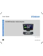
Page 1: ...User Guide Part No V4063 0013 www vinten com EN HD VRC Robotic Control System HD VRC Robotic Control System ...

Page 2: ...nges will be incorporated in new versions of the publication We are making every effort to ensure that our publications are updated on a regular basis to reflect changes to product specifications and features Should this publication not contain information on the core functionality of your product please let us know You may be able to access the latest revision of this publication from our website...

Page 3: ... 11 HD VRC Computer Connections 11 Connecting the HD VRC System 12 Control Connections 12 Camera Equipment Connections 13 Connecting the HD VRC System 13 Video and Tally Connections 14 Powering Up 15 Starting the HD VRC System 15 Launching the VRC System Application 15 Using the HD VRC 15 Using the Joystick Control Panel 15 Using the HD VRC System 16 Joystick Control Panel Buttons 16 Joystick Came...

Page 4: ...dance with local regulations CAUTION This product must be connected to a power supply of the same voltage V and current A as indicated on the product Refer to the technical specifications for the product Using alternative power sources will invalidate the system EMC liability All connections to other devices must be made using shielded cables Intended Use The HD VRC robotic control system is desig...

Page 5: ...mum of 1 m 3 ft Safety Notes for Operators Operators must familiarise themselves with the working footprint of the robotic equipment including all installed payload items lens zoom and focus controls viewfinder prompter etc to prevent inadvertent collisions or injury to personnel If personnel are too close to robotic equipment that is about to move the operator should prevent the motion from start...

Page 6: ...4 Box Contents 1 HD VRC computer 2 Joystick control panel 3 Panel power supply 4 Touch screen display NI Serial cable NI Power cable x3 NI User guide 1 2 3 NI Not Illustrated 4 ...

Page 7: ...5 Touch screen Components and Connections 5 1 2 6 7 4 1 Touch screen interface 2 Adjustable stand 3 Power button 4 USB down 5 USB up 6 Power socket 7 D SUB VGA socket 3 ...

Page 8: ...l 3 CCU iris control 4 Function buttons 5 on air indicator 10 8 9 6 Pan Tilt Zoom joystick control 7 Camera selection buttons and tally indicators x16 8 Camera control buttons Cut Fade Stop 9 Fade time control 10 Focus control Control and button functions are not present on all panel models See ...

Page 9: ...nections 1 2 3 4 5 6 7 8 9 1 Tally socket 2 Vision switcher socket serial 3 Auxiliary socket 4 Touch screen socket 5 PC socket 6 HCU socket 7 Vision switcher socket parallel 8 Auxiliary relays socket 9 Power socket 12V DC ...

Page 10: ... LHS V3976 0015 16 Left VRC SJP CCU focus RHS V3976 0019 16 Right VRC DJP CCU focus LHS V3976 0016 16 Left VRC DJP CCU focus RHS V3976 0020 16 Right MJP CCU V4008 0003 12 N A Different variant models of the joystick control panel are available to match the requirements of the user and the complexity of the VRC system installation Panels are available with or without pedestal controls X Y Z and CCU...

Page 11: ...9 HD VRC Computer Components 1 HDD indicator 2 Power indicator 3 Lockable DVD drive access panel 1 2 3 ...

Page 12: ... Component video sockets 6 SDI IN OUT video sockets 7 PS2 keyboard socket 8 Ethernet socket 9 VGA socket to touch screen 10 AC power switch 1 RS422 serial sockets COM3 4 2 USB sockets x2 3 RS232 serial sockets COM1 2 4 AC power socket Previous Version 9 ...

Page 13: ... 7 8 9 10 11 5 RS232 serial sockets COM1 2 6 HDMI socket Video capture 7 USB sockets x2 8 SDI socket Video capture 9 VGA socket to touch screen 10 Ethernet socket 11 USB sockets x2 1 AC power socket 2 AC power switch 3 DVI socket 4 RS422 serial sockets COM3 4 ...

Page 14: ...stick control panel connected together Remote camera equipment is connected using standard Ethernet connections using a powered Ethernet switch to expand the number of connections available to suit your system requirements In larger systems several VRC computer control systems including μVRC may be connected together using Ethernet connections ...

Page 15: ...trol system All camera equipment must be connected to the same Ethernet network easily expanded at any time to match your systems requirements To connect PTZ heads an additional license is required For more information refer to the VRC System User Guide part no V4063 4980 The HD VRC must be connected to a control panel variant capable of controlling all functions of the camera equipment required i...

Page 16: ...system installation a video switcher and tally interface are also connected to provide live on air camera feeds for monitoring purposes and thumbnail video capture For more information about connecting devices refer to the documentation supplied with your video switcher or tally interface ...

Page 17: ...he joystick control panel enables you to select and control connected robotic cameras Additional keys are available to select cameras and other useful functions Launching the VRC System Application When the HD VRC computer has booted up the VRC system application must be installed configured and launched before robotic cameras can be controlled For more information on the VRC system application re...

Page 18: ...ntrol cameras This guide details the use of all control panel variations and therefore some functions may not be present on your control panel If a button or control described in the text or illustrations is not present on your control panel then your model does not support that function It is also possible that during installation the functionality of the system function buttons has been customis...

Page 19: ...ovement prevents accidental movement when off 7 Pan follow When enabled controlling the Y axis causes the pedestal to travel forwards and backwards in the direction that the camera is pointing 8 X4 Disables zoom proportional mode with X4 enabled pan and tilt movements are more sensitive when zoomed in 9 Panel disable Locks all other controls on the panel to prevent accidental operation Indications...

Page 20: ...el provides the best way to smoothly control camera movement and adjustments Many control functions can be reversed in the VRC application configuration to suit a users preferences Robotic Pedestal Head and Camera Controls Using the HD VRC System ...

Page 21: ...lt Moving the joystick forward back will tilt the camera down up Zoom Rotating the joystick clockwise counter clockwise will zoom out in the camera lens Focus Rotating the Focus knob adjusts the camera lens focus 3 CCU Camera Controls Black Rotating the Black knob adjusts the camera s black level Iris Rotating the Iris knob adjusts the camera s black level 4 Time Control Fade The fade time is adju...

Page 22: ...ssary Check that all cables are connected properly Cleaning WARNING Risk of electric shock Disconnect and isolate the product from the power supply before cleaning During normal use the only cleaning required should be a regular wipe over with a dry lint free cloth Dirt accumulated during storage or periods of disuse may be removed with a vacuum cleaner Particular attention should be paid to all c...

Page 23: ...otice Joystick Control Panel Physical Data Dimensions Standard 2U rack mount enclosure depth 450 mm 17 7 in Touch screen Display Specification Refer to the documentation supplied with the product Physical Data Height 79 mm 3 1 in excludes joystick Length 483 mm 19 in Width 131 mm 5 1 in Electrical Data Power 12V DC HD VRC Computer ...

Page 24: ... equipment into an outlet on a circuit different from that to which the receiver is connected Consult the dealer or an experienced radio television technician for assistance FCC Warning Changes or modifications not expressly approved by the party responsible for compliance could void the user s authority to operate the equipment FCC Certification FCC Declaration of Conformity This product complies...

Page 25: ...al and electronic waste products By ensuring this product is disposed of correctly you will help prevent potentially negative consequences for the environment and human health The recycling of materials helps conserve natural resources Visit our website for information on how to dispose of this product and its packaging In countries outside the EU Dispose of this product at a collection point for ...

Page 26: ......

Page 27: ......

Page 28: ...www vinten com Publication No V4063 4982 01 ...

Reviews: