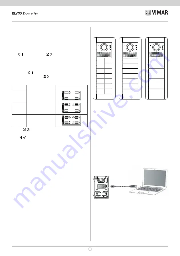
will group the buttons for the calls.
By default the speech units come with the buttons grouped in
twos horizontally to use the single axial button Art. 41110. This
button can actuate one or both mechanical buttons on the same
row.
There is also the single rocker button, Art. 41111, that lets you
actuate the single mechanical button and the double axial but
-
ton Art. 41112 which actuates up to 4 buttons.
The
(PREVIOUS) and
(NEXT) buttons change be
-
tween the possible values. If you try to go before the first or after
the last one, the speech unit will emit a tone to warn you that
there are no other valid values.
If you start from a configuration with the LEDs flashing, first
pressing the
button (PREVIOUS) will set the first possible
value, while pressing the
button (NEXT) will set the last
possible one.
Article
Description
LED
41111
Single rocker button
41110
Single axial button
(default)
41112
Double axial button
Pressing
(DEL) takes you back to the previous level, with
-
out saving any changes.
Press
(OK) to confirm what you have chosen.
Note
: For the 10 button module Art. 41010, by selecting the
Double axial button
mode, the last pair of buttons is forced to
Single axial button
.
With SaveProg you can change the grouping in a totally arbi
-
trary manner, except that the last row of each module cannot be
configured as a
Double axial button
.
The following figure outlines the configurations of the speech
unit and a button module in the three possible cases and their
respective indoor units corresponding to each group. For calls,
reference is made to the first external module.
1
3
5
7
9
11
13
1
3
5
7
9
11
13
2
4
6
8
10
12
14
1
5
9
13
Single axial
button
(default)
Single rocker
button
Double axial
button
The chosen positioning for the indoor units, with gaps in the
numbering, means you don't have to re-code the existing indoor
units or have to re-configure the existing speech units, if the
button grouping is later changed either with this procedure or
with SaveProg.
Advanced configuration (via PC)
The advanced configuration of the electronic module is per
-
formed via a PC, using the “SaveProg” Due Fili system man
-
agement software, available from the website www.vimar.com,
and connecting the electronic module to the PC via a USB-Min
-
iUSB cable.
28
41001 - 41002 - 41003 - 41004
EN


