


Disassembly Procedure
WARNING
To avoid risk of electrical shock, personal injury, or death, disconnect power to unit before servicing,
unless testing requires power.
©2007 Viking Preferred Service
45
Freezer Drawer Removal
Condition Requirements:
Freezer Baskets Removed
1. Lift drawer in front and remove from rails.
2. Remove glides by pressing in release tab and
sliding out the glides.
3. Reverse procedure for installation.
Freezer Drawer Glides Removal
Condition Requirements:
Freezer Drawer Removed
1. Remove three screws and drawer glide from each
side of the freezer cavity.
2. Reverse procedure for installation.
Ice Maker Removal
Condition Requirements:
Freezer Drawer Removed
NOTE:
Note position of fill tube before removing ice
maker.
1. Disconnect ice maker harness from rear bulkhead.
2. Loosen two screws that hold ice maker to left side of
freezer cavity.
3. Remove screw and ice maker from freezer.
4. Reverse procedure for installation.
NOTE:
Make sure to get fill tube inserted in to fill cup
fully when reassembling.
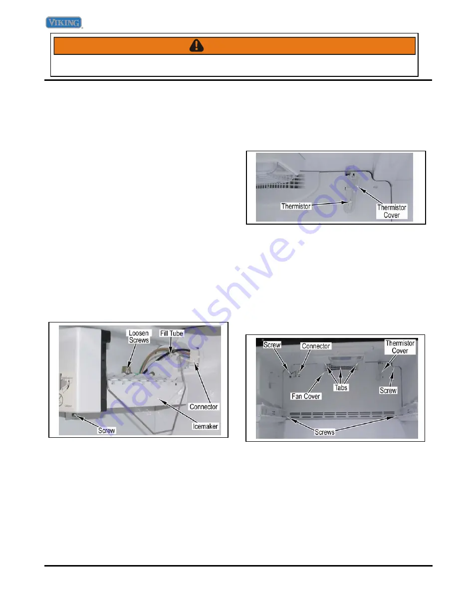
Freezer Thermistor Removal
Condition Requirements:
Freezer Drawer Removed
1. Remove thermistor cover from the back freezer
panel.
2. Cut wire at thermistor and remove thermistor.
3. Reverse procedure for installation.
Access to Evaporator Section
Condition Requirements:
Icemaker Removed
Freezer Drawer Glides Removed
1. Remove thermistor cover from the back freezer
panel.
2. Remove fan cover from back panel by using a
screwdriver to release tabs.
3. Remove four screws and evaporator cover.
4. Remove Icemaker connector from back panel.
5. Reverse procedure for installation.
Summary of Contents for DDBF036LSS
Page 18: ......
Page 50: ...Appendix A 50 2007 Viking Preferred Service NOTES ...


