background image

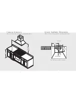
Exterior Ventilator Dimensions

27

Interior Ventilator Dimensions

26

10” (25.4 cm)
dia. duct
location

120 V

7-7/8” (20.0 cm)

1-1/8” (2.9 cm)

6” (15.2 cm)

19”

(48.3 cm)

8

23-15/16”

(60.1 cm)

120 V
power supply

5-9/16”

(14.3 cm)

A

5-1/8”

(13.0 cm)

11”

(27.9 cm)

7” (17.8 cm)
dia. duct
location

3

1-1/8”

(2.9 cm)

A

30”W.

15-3/4” (40.0 cm)

36”W.

18-3/4” (47.6 cm)

42”W.

21-3/4” (55.2 cm) 

10” (25.4 cm)
dia. duct
location

120 V

7-7/8” (20.0 cm)

1-1/8” (2.9 cm)

6” (15.2 cm)

19”

(48.3 cm)

1

23-15/16”

(60.1 cm)

120 V
power supply

5-9/16”

(14.3 cm)

A

5-1/8”

(13.0 cm)

11”

(27.9 cm)

8” (20.3 cm)*
dia. duct
location

1-1/8”

(2.9 cm)

9

A

30”W.

15-3/4” (40.0 cm)

36”W.

18-3/4” (47.6 cm)

42”W.

21-3/4” (55.2 cm) 

900 or 1200 CFM Exterior Ventilator Installation

for 30”, 36”, & 42” models

1200 or 1500 CFM Exterior Ventilator Installation

for 48” models

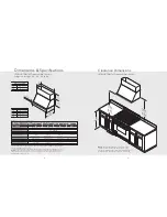
300, 440 CFM Interior Ventilator Installation

for 30”, 36”, & 42” models

(DSWB Box Wall Hoods)

(DSWB Box Wall Hoods)

880 CFM Interior Ventilator Installation

for 48” models

Top view

Top view

Top view

Top view

*8” to 10”
transition to be
acquired locally.

Summary of Contents for DCH 12''H

Page 1: ...111 Front Street Greenwood Mississippi 38930 USA 662 455 1200 For product information call 1 888 VIKING1 845 4641 or visit the Viking Web site at vikingrange com F20472 062207J UL C UL Viking Installa...

Page 2: ...E READ AND FOLLOW Before beginning please read these instructions completely and carefully Do not remove permanently affixed labels warnings or plates from the product This may void the warranty Pleas...

Page 3: ...including wet dishcloths or towels a violent steam explosion will result 4 Use an extinguisher ONLY if You know it is a Class ABC extinguisher and you already know how to operate it The fire is small...

Page 4: ...W 14 15 16 37 9 cm 36 W 17 15 16 45 6 cm 16 40 6 cm A 4 10 2 cm 120 V 7 17 8 cm dia duct location 9 3 4 24 8 cm 460 CFM Interior Ventilator Installation DCH 12 H Classic Chimney Wall Hoods w Standard...

Page 5: ...is 75 ft NOTE Maximum amp rating for hoods includes recommended ventilator kit rating All products must be hard wired with 2 wire with ground An interior or exterior power ventilator kit must be purch...

Page 6: ...cm 1 1 2 3 8 cm 1 1 2 3 8 cm A 1 1 2 3 8 cm 120V power supply Classic Chimney w Ledge Classic Chimney 6 15 2 cm C B A 30 W 10 25 4 cm 33 W 10 25 4 cm 36 W 12 30 5 cm 39 W 12 30 5 cm 42 W 12 30 5 cm 4...

Page 7: ...er ventilator kit must be purchased for installation with all Designer hoods DCIH Classic Chimney Island Hoods Description 36 42 54 Duct cover width 12 30 5 cm 12 30 5 cm 18 45 7 cm Duct cover depth 1...

Page 8: ...duct location 1 18 45 7 cm 6 15 2 cm 120 V power supply 7 17 8 cm 15 38 1 cm 4 3 4 12 1 cm 4 3 4 12 1 cm 12 30 5 cm A 10 25 4 cm dia duct location 15 38 1 cm 9 12 30 5 cm 120 V power supply A 36 W 17...

Page 9: ...xterior power ventilator kit must be purchased for installation with all Designer hoods DTWS Slim Traditional Wall Hoods Description 30 36 42 48 Duct cover width 12 30 5 cm 12 30 5 cm 12 30 5 cm 20 50...

Page 10: ...dels 120 V power supply 5 9 16 14 3 cm A 5 1 8 13 0 cm 11 27 9 cm 7 17 8 cm dia duct location 3 1 1 8 2 9 cm A 30 W 15 3 4 40 0 cm 36 W 18 3 4 47 6 cm 42 W 21 3 4 55 2 cm 300 or 440 CFM Interior Venti...

Page 11: ...longer duct runs Max duct run is 75 ft NOTE Maximum amp rating for hoods includes recommended ventilator kit rating All products must be hard wired with 2 wire with ground An interior or exterior powe...

Page 12: ...16 8 cm 3 7 62 cm 2 1 2 6 35 cm Tall Traditional with Ledge 120 V Tall Traditional Ledgeless 10 24 8 cm dia duct location A 5 5 16 15 1 cm 3 7 6 cm 2 1 2 6 4 cm Tall Traditional with Ledge Tall Tradi...

Page 13: ...entilator be used with longer duct runs Max duct run is 75 ft NOTE Maximum amp rating for hoods includes recommended ventilator kit rating All products must be hard wired with 2 wire with ground An in...

Page 14: ...1 8 2 9 cm 6 15 2 cm 19 48 3 cm 1 23 15 16 60 1 cm 120 V power supply 5 9 16 14 3 cm A 5 1 8 13 0 cm 11 27 9 cm 8 20 3 cm dia duct location 1 1 8 2 9 cm 9 A 30 W 15 3 4 40 0 cm 36 W 18 3 4 47 6 cm 42...

Page 15: ...is required Electrical Supply Run 120 VAC electrical wiring from service panel to installation location See specification pages for the maximum amp requirements Roof cap 7 round duct Duct cover or sof...

Page 16: ...over rear lip Slide filter front over front lip Push filter rear up then slide back over rear lip 2 1 3 10 3 4 2 Place duct cover top inside duct cover base and lower until desired height is found Mar...

Page 17: ...aker box 1 1 2 9 10 Slide filter front over front lip Push filter rear up then slide back over rear lip 2 1 11 3 Assemble brackets to mesh filters and insert charcoal filters 2 1 2 Remove damper and d...

Page 18: ...ct cover using screws provided make sure top mounting screws are secured into soffit or cabinet frame Use additional mounting screws if necessary To install ventillation kit refer to ventillation kit...

Page 19: ...ction to breaker box 1 2 2 Measure distance from ceiling to canopy Slide duct cover in place and fasten from inside canopy using the sheet metal screws provided Duct Cover Option DTWL DTWN Tall Tradit...

Page 20: ...duct cover to canopy with screws provided Lower duct cover into position on canopy Duct Cover Required DSWB Box Wall Hoods Only 2 1 3 7 1 2 1 2 3 8 Slide filter front over front lip Push filter rear u...

Page 21: ...ront lip Push filter rear up then slide back over rear lip Check framing where cutout will be NOTE 200 lb limit Cut appropriate size hole in ceiling Either 7 or 10 depending on your specific unit and...

Page 22: ...__ Serial number _________________________________________ Date of purchase _________________________________________ Date installed _________________________________________ Dealer s name ___________...

Reviews: