9
GRILLE ASSEMBLY/INSTALLATION
PROFESSIONAL MODEL
PBRTGK72SS
Before moving the refrigerators in place, confirm the finished dimensions, electrical, and plumbing locations, minimum
door clearances, and door panel installations are accurate. (See Installation Instructions provided with refrigerators).
1. Position refrigerators in front of cutout.
2. Remove the top air grille assemblies from both of the units
a. Remove full length center grille blade by lifting up and pulling forward.
b. Remove the grille/end cap assembly by removing two (2) screws.
c. Remove grille brackets by removing four (4) screws in each grille assembly.
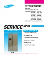
REAR VIEW OF
GRILLE ASSEMBLY
TOP VIEW OF GRILLE ASSEMBLY
72” (182.9 cm)
30 1/32” (76.3 cm)
3 3/8”
(8.6 cm)
4 7/32”
(10.7 cm)
30 7/8“ (78.4 cm)
Power
Switch
Showroom
Switch
3. Verify operation by plugging in
power cord.
Power switch
will be shipped in the ON
position and showroom
switch will be in the ON
position.
(If showroom switch
is switched to the “OFF”
position, showroom mode is
engaged and power is shut off
to the compressor. This mode
is for showroom display only.)