background image


55 


3-2 ACL 


3-2.1 Ports 

The Vi3026 switch access control list (ACL) is probably the most commonly used 
object in the IOS. It is used for packet filtering but also for selecting types of traffic 
to be analyzed, forwarded, or influenced in some way. The ACLs are divided into 
EtherTypes - IPv4, ARP protocol, MAC, and VLAN parameters. In this section, we will 
go over the standard and extended access lists for TCP/IP. As you create ACEs for 
ingress classification, you can assign a policy for each port. The policy number is 1-8. 
However, each policy can be applied to any port. This makes it very easy to 
determine what type of ACL policy you will be working with. 


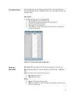
The section describes how to configure the ACL parameters (ACE) of the each switch 
port. These parameters will affect frames received on a port, unless the frame 
matches a specific ACE. 

Web Interface  

To configure the ACL Ports Configuration in the web interface: 

1.


Click Configuration, ACL, then Ports. 

2.


Scroll the specific parameter value to select the correct value for port ACL 
setting.  

3.


Click “Apply” to save the setting. 

4.


If you want to cancel the setting, then you need to click the reset button to 
revert back to previously saved values. 

5.


After your configuration is complete, then you could see the counter of the 
port. You could click refresh to update the counter or clear the information. 

Figure 3-2.1:  The ACL Ports Configuration 


Summary of Contents for MaxiiNet VI3026

Page 1: ... reserved All brand and product names are trademarks or registered trademarks of their respective companies MaxiiNetTM VI3026 Operational Manual 20 GE PoE Plus 4 GE PoE Plus Combo SFP 2 GE SFP L2 26 Port Managed Switch Release 2 44 ...

Page 2: ...ol SNMP The following conventions are used throughout this guide to show information NOTE Emphasizes important information or calls your attention to related features or instructions WARNING Alerts you to a potential hazard that could cause personal injury CAUTION Alerts you to a potential hazard that could cause loss of data or damage the system or equipment See the Customer Support Warranty book...

Page 3: ...interference to radio communications To assure continued compliance example use only shielded interface cables when connection to computer or peripheral devices Any changes or modifications not expressly approved by the party responsible for compliance could void the user s authority to operate the equipment This device complies with Part 15 of the FCC Rules Operation is subject to the following t...

Page 4: ...on 16 2 1 1 Information 16 2 1 2 Configuration 18 2 2 Time 19 2 2 1 Manual 19 2 2 2 NTP 21 2 3 Account 22 2 3 1 Users 22 2 3 2 Privilege Level 24 2 4 IP 26 2 4 1 IPv4 26 2 4 2 IPv6 28 2 5 Syslog 29 2 5 1 Configuration 29 2 5 2 Log 30 2 5 3 Detailed 31 2 6 SNMP 32 2 6 1 System 32 2 6 2 Configuration 33 2 6 3 Communities 34 2 6 4 Users 35 2 6 5 Groups 37 2 6 6 Views 38 2 6 7 Access 39 2 6 8 Trap 41 ...

Page 5: ...ning Tree 76 3 4 1 Bridge Settings 76 2 4 2 MSTI Mapping 79 3 4 3 MSTI Priorities 81 3 4 4 CIST Ports 82 3 4 5 MSTI Ports 84 3 4 6 Bridge Status 86 3 4 7 Port Status 87 3 4 8 Port Statistics 88 3 5 IGMP Snooping 89 3 5 1 Basic Configuration 89 3 5 2 VLAN Configuration 91 3 5 3 Port Group Filtering 93 3 5 4 Status 95 3 5 5 Group Information 97 3 5 6 IPv4 SSM Information 98 3 6 MLD Snooping 100 3 6 ...

Page 6: ... PoE 132 3 9 1 Configuration 132 3 9 2 Status 134 3 9 3 Power Delay 136 3 9 4 Auto Checking 138 3 9 5 Scheduling 140 3 10 Filtering Data Base 141 3 10 1 Configuration 141 3 10 2 Dynamic MAC Table 144 3 11 VLAN 145 3 11 1 VLAN Membership 145 3 11 2 Ports 147 3 11 3 Switch Status 149 3 11 4 Port Status 151 3 11 5 Private VLANs 153 3 11 6 MAC Based VLAN 155 3 11 7 Protocol Based VLAN 158 3 12 Voice V...

Page 7: ... 191 3 15 11 QCL Status 195 3 15 12 Storm Control 197 3 16 S Flow Agent 198 3 16 1 Collector 198 3 16 2 Sampler 200 3 17 Loop Protection 202 3 17 1 Configuration 202 3 17 2 Status 204 3 18 Single IP 205 3 18 1 Configuration 205 3 18 2 Information 206 3 19 Easy Port 207 3 20 Mirroring 210 3 21 Trap Event Severity 212 3 22 UPnP 213 Chapter 4 Security 214 4 1 IP Source Guard 214 4 1 1 Configuration 2...

Page 8: ...ort Security 251 4 7 1 Limit Control 251 4 7 2 Switch Status 254 4 7 3 Port Status 256 4 8 Access Management 257 4 8 1 Configuration 257 4 8 2 Statistics 259 4 9 SSH 260 4 10 HTTPs 261 4 11 Auth Method 262 Chapter 5 Maintenance 263 5 1 Restart Device 263 5 2 Firmware 264 5 2 1 Firmware Upgrade 264 5 2 2 Firmware Selection 265 5 3 Save Restore 267 5 3 1 Factory Defaults 267 5 3 2 Save Start 268 5 3...

Page 9: ...nostics 273 5 5 1 Ping 273 5 5 2 Ping6 274 Glossary of Web based Management 275 A 275 C 276 D 276 E 278 F 278 H 279 I 279 L 280 M 281 N 282 O 282 P 283 Q 284 R 284 S 285 T 286 U 286 V 287 Contact Information 288 ...

Page 10: ...rmation and applications effectively It provides the ideal combination of affordability and capabilities for entry level networking including small business or enterprise application to help you create a more efficient and better connected workforce Vi3026 web managed switches provide 26 ports in a single device The specifications are highlighted as follows L2 features provide better manageability...

Page 11: ...t it s the safer option The Vi3026 supports a simple user management function to allow only one administrator to configure the system at any one time The use of simultaneous administrators could result in unpredictable operation Additional users even with administrator s identity should only monitor the system Those who have no administrator s identity can only monitor the system It is suggested r...

Page 12: ...vide IP addresses to the switch the switch s default IP is 192 168 1 1 Figure 1 The Login Page NOTE If you need to configure the function or parameter you can refer to the detail in the User Guide You could also access the switch and click on help under the web GUI The switch will pop up the simple help content to teach you how to set the parameters ...

Page 13: ...13 Vi3026 Web Help Function 00 40 D8 55 35 57 Vi3026 ...

Page 14: ...better for 100BASE TX connections The RJ 45 ports on the switch support automatic MDI MDI X pin out configuration You can use standard straight through twisted pair cables to connect to any other network devices E g PCs servers switches routers or hubs See Appendix B for further information on cabling CAUTION Do not plug a phone jack connector into an RJ 45 port This will damage the switch Use onl...

Page 15: ...f the newer equipment racks It is actually part of the patch panel Instructions for making connections in the wiring closet with this type of equipment are as follows Step 1 Attach one end of a patch cable to an available port on the switch and the other end to the patch panel Step 2 If not already in place attach one end of a cable segment to the back of the patch panel where the punch down block...

Page 16: ...sion Serial Number Host IP Address Host Mac Address Device Port RAM Size Flash Size and With this information you will know the software version used MAC address serial number how many ports are good and so on This will be helpful during any malfunctions The switch system information is provided here Web Interface To configure System Information in the web interface 1 Click SYSTEM System and Infor...

Page 17: ...yphen is the version of electronic hardware The one after the hyphen is the version of mechanical Serial number The serial number is assigned by the Manufacture Host IP address This is IP address of the switch Subnet Mask This displays the IP subnet mask assigned to the device Gateway IP Address This displays the default gateway IP address assigned to the device Host MAC address This is the Ethern...

Page 18: ... how to contact this person The allowed string length is 0 to 255 and the allowed content is the ASCII characters from 32 to 126 System Name An administratively assigned name for this managed node By convention this is the node s fully qualified domain name A domain name is a text string drawn from the alphabet A Za z digits 0 9 minus sign No space characters are permitted as part of a name The fi...

Page 19: ...d automatic ways to set the system time via NTP Manual setting is simple and you just input Year Month Day Hour Minute and Second within the valid value range indicated in each item Web Interface To configure Time in the web interface 1 Click Time then Manual 2 Specify the time parameter in manual parameters 3 Click Apply Figure 2 2 1 The Time Configuration ...

Page 20: ...our after one minute at the time since it passed over The switch supports valid configurable day light saving time is 5 5 step one hour The zero for this parameter means it need not have to adjust current time equivalent to in act daylight saving You don t have to set the starting ending date If you set daylight saving to be non zero you have to set the starting ending date Otherwise the daylight ...

Page 21: ...e from 12 to 13 step 1 hour Default Time zone 8 Hrs Web Interface To configure Time in the web interface 1 Click SYSTEM then NTP 2 Specify the Time parameter in manual parameters 3 Click Apply Figure 2 2 2 The NTP configuration Server 1 to 5 Provides the NTP IPv4 or IPv6 address of this switch IPv6 address is in 128 bit records represented as eight fields of up to four hexadecimal digits with a co...

Page 22: ...tor guest identity in the field of Authorization in advance before configuring the username and password Only one administrator is allowed to exist and unable to be deleted In addition up to 4 guest accounts can be created This page provides an overview of the current users Currently the only way to login as another user on the web server is to close and reopen the browse Web Interface To configur...

Page 23: ...15 it can access all groups e g that is granted the fully control of the device But others value need to refer to each group privilege level User s privilege should be same or greater than the group privilege level to have the access of that group By default setting most groups privilege level 5 has the read only access and privilege level 10 has the read write access For system maintenance softwa...

Page 24: ...LDP MED MAC Table MRP MVR MVRP Maintenance Mirroring POE Ports Private VLANs QoS SNMP Security Spanning Tree System Trap Event VCL VLANs and Voice VLAN Privilege Levels from 1 to 15 Web Interface To configure Privilege Level in the web interface 1 Click SYSTEM Account then Privilege Level 2 Specify the privilege parameter 3 Click Apply Figure 2 3 2 The Privilege Level Configuration ...

Page 25: ...rt Security System Access Management ACL HTTPS SSH and Auth Method Account Users and Privilege Level Diagnostics Ping Ping6 and VeriPHY Maintenance System Reboot System Restore Default Configuration Save Export Import Configuration and Firmware upgrade Privilege Levels Every group has an authorization Privilege level for the following sub groups configuration read only configuration execute read w...

Page 26: ... Protocol IPv6 which would have 128 bits Internet Protocol addresses This number can be represented roughly by a three with thirty nine zeroes after it However IPv4 is still the protocol of choice for most of the Internet The IPv4 address for the switch could be obtained via DHCP Server for VLAN 1 To manually configure an address you need to change the switch s default settings to values that are ...

Page 27: ...S lookup IP Address Provides the IP address of this switch in dotted decimal notation IP Mask Provides the IP mask of this switch dotted decimal notation IP Gateway Provides the IP address of the router in dotted decimal notation VLAN ID Provides the managed VLAN ID The allowed range is 1 to 4095 DNS Server Provides the IP address of the DNS Server in dotted decimal notation DNS Proxy When DNS pro...

Page 28: ...router may delay responding to a router solicitation for a few seconds the total time needed to complete auto configuration can be significantly longer Address Provides the IPv6 address of this switch IPv6 address is in 128 bit records represented as eight fields of up to four hexadecimal digits with a colon separating each field For example fe80 215 c5ff fe03 4dc7 The symbol is a special syntax t...

Page 29: ...cates the server mode operation When the mode operation is enabled the syslog message will send out to syslog server The syslog protocol is based on UDP communication and received on UDP port 514 The syslog server will not send acknowledgments back sender since UDP is a connectionless protocol and it does not provide acknowledgments The syslog packet will always send out even if the syslog server ...

Page 30: ...following level types are supported 0 Emergency System is unusable 1 Alert Action must be taken immediately 2 Critical Critical conditions 3 Error Error conditions 4 Warning Warning conditions 5 Notice Normal but significant conditions 6 Information Information messages 7 Debug Debug level messages Time It will display the log record by device time The time of the system log entry Message It will ...

Page 31: ...on in the web interface 1 Click Syslog then Detailed Log 2 Display the log information Figure 2 5 3 The Detailed System Log Information ID The ID 1 of the system log entry Message The detailed message of the system log entry Upper right icon Refresh clear You can click them to refresh the system log or clear them manually Click other buttons to move to the next or previous page ...

Page 32: ...e Trap Host IP Address Trap and all MIB counters will be ignored This section describes how to configure SNMP System on the switch This function is used to configure SNMP settings community name trap host and public traps as well as the throttle of SNMP A SNMP manager must pass the authentication by identifying both community names then it can access the MIB information of the target device Both p...

Page 33: ...SNMPv2c If SNMP version is SNMPv3 the community string will be associated with SNMPv3 communities table It provides more flexibility to configure security name than a SNMPv1 or SNMPv2c community string In addition to community string a particular range of source addresses can be used to restrict source subnet Set Community Indicates the community writes access string to permit access to SNMP agent...

Page 34: ...2 The SNMPv1 v2 Communities Security Configuration Delete Check to delete the entry It will be deleted during the next save Community Indicates that the community access string permit access to SNMPv3 agent The allowed string length is 1 to 32 and the allowed content is ASCII characters from 33 to 126 The community string will be treated as security name and map a SNMPv1 or SNMPv2c community strin...

Page 35: ...aracters from 33 to 126 Security Level Indicates the security model that this entry should belong to Possible security models are NoAuth NoPriv No authentication and no privacy Auth NoPriv Authentication and no privacy Auth Priv Authentication and privacy The value of security level cannot be modified if entry already exists That means it must first be ensured that the value is set correctly Authe...

Page 36: ...d content is ASCII characters from 33 to 126 Privacy Protocol Indicates the privacy protocol that this entry should belong to Possible privacy protocols are None No privacy protocol DES An optional flag to indicate that this user uses DES authentication protocol Privacy Password A string of number identifies the privacy password phrase The allowed string length is 8 to 32 and the allowed content i...

Page 37: ...The SNMP Groups Configuration Delete Check to delete the entry It will be deleted during the next save Security Model Indicates the security model that this entry should belong to Possible security models are V1 Reserved for SNMPv1 V2c Reserved for SNMPv2c Usm User based Security Model USM Security Name A string identifying the security name that this entry should belong to The allowed string leng...

Page 38: ...ave View Name A string identifying the view name that this entry should belong to The allowed string length is 1 to 32 and the allowed content is ASCII characters from 33 to 126 View Type Indicates the view type that this entry should belong to Possible view types are Included An optional flag to indicate that this view subtree should be included Excluded An optional flag to indicate that this vie...

Page 39: ...he SNMP access parameters 4 Click Apply 5 If you want to modify or clear the setting then click Reset Figure 2 6 6 The SNMP Accesses Configuration Delete Check to delete the entry It will be deleted during the next save Group Name A string identifying the group name that this entry should belong to The allowed string length is 1 to 32 and the allowed content is ASCII characters from 33 to 126 Secu...

Page 40: ...bjects for which this request may potentially set new values The allowed string length is 1 to 32 and the allowed content is ASCII characters from 33 to 126 Write View Name The name of the MIB view defining the MIB objects for which this request may potentially set new values The allowed string length is 1 to 32 and the allowed content is ASCII characters from 33 to 126 Button Add new access Click...

Page 41: ... trap information then check Apply Max Group Number 6 Web Interface To configure SNMP Trap setting 1 Click SNMP then Trap 2 Display the SNMP Trap Hosts information table 3 Choose an entry to display and modify the detail parameters or click delete button to delete the trap hosts entry Figure 2 6 7 The SNMP Trap Host Configuration ...

Page 42: ...mation warnings and errors Warning Send warnings and errors Error Send errors Security Level There are three kinds of choices NoAuth NoPriv No authentication and no privacy Auth NoPriv Authentication and no privacy Auth Priv Authentication and privacy Authentication Protocol You can choose MD5 or SHA for authentication Authentication Password The length of MD5 Authentication Password is restricted...

Page 43: ...us in the function This chapter describes how to view the current port configuration and how to configure ports to non default settings including Linkup Linkdown Speed Current and configured Flow Control Current Rx Current Tx and Configured Maximum Frame Size Excessive Collision Mode Power Control Web Interface To configure a Current Port Configuration in the web interface 1 Click Configuration Po...

Page 44: ...duplex mode 100Mbps FDX Forces the cu port in 100Mbps full duplex mode 1Gbps FDX Forces the cu port in 1Gbps full duplex mode SFP_Auto_AMS Automatically determines the speed of the SFP Note There is no standardized way to do SFP auto detect so here it is done by reading the SFP rom Due to the missing standardized way of doing SFP auto detect some SFPs might not be detectable The port is set in AMS...

Page 45: ...e maximum frame size allowed for the switch port including FCS Excessive Collision Mode Configures port transmit collision behavior Discard Discards frame after 16 collisions default Restart Restarts back off algorithm after 16 collisions Power Control The Usage column shows the current percentage of the power consumption per port The Configured column allows for changing the power savings mode pa...

Page 46: ...web interface 1 Click Configuration Port then Port Description 2 Specify the detail port alias or description an alphanumeric string describing the full name and version identification for the system s hardware type software version and networking application 3 Click Apply Figure 3 1 2 The Port Configuration Port This is the logical port number for this row Description Enter up to 47 characters to...

Page 47: ...Port Statistics Overview Port The logical port for the settings contained in the same row Packets The number of received and transmitted packets per port Bytes The number of received and transmitted bytes per port Errors The number of frames received in error and the number of incomplete transmissions per port Drops The number of frames discarded due to ingress or egress congestion Filtered The nu...

Page 48: ...ew 3 If you want to auto refresh the information then select Auto refresh 4 Click Refresh to refresh the port detailed statistics or clear all information when you click Clear Figure 3 1 4 The Port Detail Statistics Overview Auto refresh Evoke the auto refresh to refresh the port statistics information automatically Upper left scroll bar To scroll which port to display the port statistics with Por...

Page 49: ...ignment errors Rx Undersize The number of short 1 frames received with valid CRC Rx Oversize The number of long 2 frames received with valid CRC Rx Fragments The number of short 1 frames received with invalid CRC Rx Jabber The number of long 2 frames received with invalid CRC Rx Filtered The number of received frames filtered by the forwarding process Short frames are frames that are smaller than ...

Page 50: ...n then you need to evoke the Auto refresh 3 Click Refresh to refresh the queuing counters or clear all information when you click Clear Figure 3 1 5 The Queuing Counters Overview Port The logical port for the settings contained in the same row Qn Qn is the QoS queue number per port Q0 is the lowest priority queue Rx Tx The number of received and transmitted packets per queue Auto refresh To evoke ...

Page 51: ...on Figure 3 1 6 The SFP Information Overview Connector Type Displays the connector type e g UTP SC ST LC and so on Fiber Type Displays the fiber mode e g Multi Mode or Single Mode Tx Central Wavelength Displays the fiber optical transmitting central wavelength e g 850nm 1310nm 1550nm and so on Baud Rate Displays the maximum baud rate of the fiber module supported e g 10M 100M 1G and so on Vendor O...

Page 52: ...ufacturer Date Code Shows the date this SFP module was made Temperature Shows the current temperature of SFP module Vcc Shows the working DC voltage of SFP module Mon1 Bias mA Shows the Bias current of SFP module Mon2 TX PWR Shows the transmit power of SFP module Mon3 RX PWR Shows the receiver power of SFP module ...

Page 53: ...re ready to be transmitted Instead the circuit is queued until 3000 bytes of data are ready to be transmitted To avoid a large delay in case that data less than 3000 bytes shall be transmitted data are always transmitted after 48 us to give a maximum latency of 48 us the wakeup time If desired it is possible to minimize the latency for specific frames by mapping the frames to a specific queue done...

Page 54: ...ical EEE port EEE Enabled Controls whether EEE is enabled for this switch port EEE Urgent Queues Queues set will activate transmission of frames as soon as any data is available Otherwise the queue will postpone the transmission until 3000 bytes are ready to be transmitted Buttons Apply Click Apply to save changes Reset Click Reset to undo any changes made locally and revert back to previously sav...

Page 55: ... determine what type of ACL policy you will be working with The section describes how to configure the ACL parameters ACE of the each switch port These parameters will affect frames received on a port unless the frame matches a specific ACE Web Interface To configure the ACL Ports Configuration in the web interface 1 Click Configuration ACL then Ports 2 Scroll the specific parameter value to selec...

Page 56: ...his port The allowed values are Enabled Frames received on the port are stored in the System Log Disabled Frames received on the port are not logged The default value is Disabled Please note that the system log memory size and logging rate is limited Shutdown Specifies the port shut down operation of this port The allowed values are Enabled If a frame is received on the port the port will be disab...

Page 57: ...croll the unit with pps or kbps 4 Click Apply to save the setting 5 If you want to cancel the setting click the reset button to revert back to previously saved values Figure 3 2 2 The ACL Rate Limiter Configuration Rate Limiter ID The rate limiter ID for the settings contained in the same row Rate The allowed values are 0 3276700 in pps or 0 100 200 300 1000000 in kbps Unit Specify the rate unit T...

Page 58: ...switch Click on the lowest plus sign to add a new ACE to the list The reserved ACEs used for internal protocol cannot be edited or deleted The order sequence cannot be changed and the priority is highest Web Interface To configure Access Control List in the web interface 1 Click Configuration ACL then Configuration 2 Click the button to add a new ACL or use the other ACL modification buttons to sp...

Page 59: ...e the IPv4 frames won t match the ACE with Ethernet type IPv6 Only IPv6 frames can match this ACE Notice the IPv6 frames won t match the ACE with Ethernet type Action Specify the action to take with a frame that hits this ACE Permit The frame that hits this ACE is granted permission for the ACE operation Deny The frame that hits this ACE is dropped Rate Limiter Indicates the rate limiter number of...

Page 60: ...is value A field for entering a DMAC value appears Counter When Specific is selected for the DMAC filter you can enter a specific destination MAC address The legal format is xx xx xx xx xx xx xx xx xx xx xx xx or xxxxxxxxxxxx x is a hexadecimal digit A frame that hits this ACE matches this DMAC value VLAN Parameters 802 1Q Tagged Specifies whether frames can hit the action according to the 802 1Q ...

Page 61: ...Mask When Network is selected for the sender IP filter you can enter a specific sender IP mask in dotted decimal notation Target IP Filter Specifies the target IP filter for this specific ACE Any No target IP filter is specified target IP filter is don t care Host Target IP filter is set to Host Specifies the target IP address in the Target IP Address field that appears Network Target IP filter is...

Page 62: ...P Protocol Filter Specifies the IP protocol filter for this ACE Any No IP protocol filter is specified don t care Specific If you want to filter a specific IP protocol filter with this ACE choose this value A field for entering an IP protocol filter appears ICMP Select ICMP to filter IPv4 ICMP protocol frames Extra fields for defining ICMP parameters will appear These fields are explained later in...

Page 63: ...ddress and SIP Mask fields that appear SIP Address When Host or Network is selected for the source IP filter you can enter a specific SIP address in dotted decimal notation SIP Mask When Network is selected for the source IP filter you can enter a specific SIP mask in dotted decimal notation DIP Filter Specifies the destination IP filter for this ACE Any No destination IP filter is specified desti...

Page 64: ... is selected for the TCP UDP source filter you can enter a specific TCP UDP source value The allowed range is 0 to 65535 A frame that hits this ACE matches this TCP UDP source value TCP UDP Source Range When Range is selected for the TCP UDP source filter you can enter a specific TCP UDP source range value The allowed range is 0 to 65535 A frame that hits this ACE matches this TCP UDP source value...

Page 65: ...alue for this ACE 0 TCP frames where the ACK field is set must not be able to match this entry 1 TCP frames where the ACK field is set must be able to match this entry Any Any value is allowed don t care TCP URG Specifies the TCP Urgent Pointer field significant URG value for this ACE 0 TCP frames where the URG field is set must not be able to match this entry 1 TCP frames where the URG field is s...

Page 66: ...ly to apply changes Reset Click Reset to undo any changes made locally and revert back to previously saved values Auto refresh Click Auto refresh to refresh the information automatically Upper right icon Refresh clear Remove All You can click them to refresh the ACL configuration or clear them manually Click other buttons to remove all ACL configurations on the table ...

Page 67: ...y frame type EType The ACE will match Ethernet Type frames Note that an Ethernet Type based ACE will not get matched by IP and ARP frames ARP The ACE will match ARP RARP frames IPv4 The ACE will match all IPv4 frames IPv4 ICMP The ACE will match IPv4 frames with ICMP protocol IPv4 UDP The ACE will match IPv4 frames with UDP protocol IPv4 TCP The ACE will match IPv4 frames with TCP protocol IPv4 Ot...

Page 68: ... first packet that matched the specific ACE to CPU Counter The counter indicates the number of times the ACE was hit by a frame Conflict Indicates the hardware status of the specific ACE The specific ACE is not applied to the hardware due to hardware limitations Auto refresh Evoke Auto refresh to refresh the information automatically Combined Selects the ACL status from this drop down list Upper r...

Page 69: ...ndwidth aggregation Ports using Static Trunk as their trunk method can choose their unique Static GroupID to form a logic trunked port The benefit of using Static Trunk method is that a port can immediately become a member of a trunk group without any handshaking with its peer port This is also a disadvantage because the peer ports of your static trunk group may not know that they should be aggreg...

Page 70: ...bled TCP UDP Port Number The TCP UDP port number can be used to calculate the destination port for the frame Check to enable the use of the TCP UDP Port Number or uncheck to disable By default the TCP UDP Port Number is enabled Aggregation Group Configuration Group ID Indicates the group ID for the settings contained in the same row Group ID Normal indicates there is no aggregation Only one group ...

Page 71: ...rt configurations A LACP trunk group with more than one ready member ports is a real trunked group A LACP trunk group with only one or less than one ready member ports is not a real trunked group Web Interface To configure the Trunk Aggregation LACP parameters in the web interface 1 Click Configuration LACP then Configuration 2 Evoke to enable or disable the LACP on the port of the switch Scroll t...

Page 72: ...ey as appropriate by the physical link speed 10Mb 1 100Mb 2 1Gb 3 Using the Specific setting a user defined value can be entered Ports with the same key value can participate in the same aggregation group while ports with different keys cannot Role The Role shows the LACP activity status Active will transmit LACP packets each second while Passive will wait for a LACP packet from a partner speak if...

Page 73: ... 2 2 The LACP System Status Aggr ID The Aggregation ID associated with this aggregation instance For LLAG the id is shown as isid aggr id and for GLAGs as aggr id Partner System ID The system ID MAC address of the aggregation partner Partner Key The Key that the partner has assigned to this aggregation ID Last changed The time since this aggregation changed Local Ports Shows which ports are a part...

Page 74: ...s enabled and the port link is up No means that LACP is not enabled or that the port link is down Backup means that the port could not join the aggregation group but will join if other port leaves Meanwhile the LACP status is disabled Key The key assigned to this port Only ports with the same key can aggregate together Aggr ID The Aggregation ID assigned to this aggregation group IDs 1 and 2 are G...

Page 75: ...d to evoke the Auto refresh 3 Click Refresh to refresh the LACP Statistics Figure 3 3 2 4 The LACP Statistics Port The switch port number LACP Received Shows how many LACP frames have been received at each port LACP Transmitted Shows how many LACP frames have been sent from each port Discarded Shows how many unknown or illegal LACP frames have been discarded at each port Auto refresh Evoke Auto re...

Page 76: ...l root ports and designated ports and disables all other ports Network packets are therefore only forwarded between root ports and designated ports eliminating any possible network loops Once a stable network topology has been established all bridges listen for Hello BPDUs Bridge Protocol Data Units transmitted from the Root Bridge If a bridge does not get a Hello BPDU after a predefined interval ...

Page 77: ...itted by the bridge when it is the root bridge Valid values are in the range 6 to 40 seconds and MaxAge must be FwdDelay 1 2 Maximum Hop Count This defines the initial value of remaining hops for MSTI information generated at the boundary of an MSTI region It defines how many bridges a root bridge can distribute its BPDU information to Valid values are in the range 6 to 40 hops Transmit Hold Count...

Page 78: ...d and re enabled for normal STP operation The condition is also cleared by a system reboot Port Error Recovery Timeout The time to pass before a port in the error disabled state can be enabled Valid values are between 30 and 86400 seconds 24 hours Buttons Apply Click Apply to save changes Reset Click Reset to undo any changes made locally and revert back to previously saved values ...

Page 79: ... left empty e g not having any VLANs mapped to it This section allows the user to inspect and change the current STP MSTI bridge instance priority configurations Web Interface To configure the Spanning Tree MSTI Mapping parameters in the web interface 1 Click Configuration Spanning Tree then MSTI Mapping 2 Specify the configuration identification parameters in the field Specify the VLANs Mapped bl...

Page 80: ...e MSTI configuration named above This must be an integer between 0 and 65535 MSTI Mapping MSTI The bridge instance The CIST is not available for explicit mapping as it will receive the VLANs not explicitly mapped VLANs Mapped The list of VLANs mapped to the MSTI The VLANs must be separated with comma and or space A VLAN can only be mapped to one MSTI An unused MSTI should just be left empty e g no...

Page 81: ...ties parameters in the web interface 1 Click Configuration Spanning Tree then MSTI Priorities 2 Scroll the Priority maximum is 240 The default is 128 3 Click Save to apply the setting 4 If you want to cancel the setting click the reset button to revert back to previously saved values Figure 3 4 3 The MSTI Configuration MSTI The bridge instance The CIST is the default instance which is always activ...

Page 82: ...ee CIST Ports parameters in the web interface 1 Click Configuration Spanning Tree then CIST Ports 2 Scroll and evoke to set all parameters of CIST Aggregated Port Configuration 3 Evoke to enable or disable the STP then scroll and evoke to set all parameters of the CIST normal Port configuration 4 Click Apply to save the setting 5 If you want to cancel the setting click the reset button to revert b...

Page 83: ...work administrator to prevent bridges external to a core region of the network influence the spanning tree active topology possibly because those bridges are not under the full control of the administrator This feature is also known as Root Guard Restricted TCN If enabled it causes the port not to propagate received topology change notifications and topology changes to other ports It can also caus...

Page 84: ...ns It contains MSTI port settings for physical and aggregated ports Web Interface To configure the Spanning Tree MSTI Port Configuration parameters in the web interface 1 Click Configuration Spanning Tree then MSTI Ports 2 Scroll to select the MST1 or other MSTI Port 3 Click Set to set the detail parameters of the MSTI Ports 4 Scroll to set all parameters of the MSTI port configuration 5 Click App...

Page 85: ...a user defined value can be entered The path cost is used when establishing the active topology of the network Lower path cost ports are chosen as forwarding ports in favor of higher path cost ports Valid values are in the range 1 to 200000000 Priority Controls the port priority This can be used to control priority of ports having identical port cost see above Buttons Apply Click Apply to save cha...

Page 86: ...s Figure 3 4 6 The STP Bridges status MSTI MSTI is the bridge instance It s also a link to the STP detailed bridge status Bridge ID The bridge ID of this bridge instance Root ID The bridge ID of the currently elected root bridge Root Port The switch port currently assigned the root port role Root Cost It s the root path cost It is zero for the root bridge For all other bridges it is the sum of the...

Page 87: ...h 3 Click Refresh to refresh the STP Bridges Figure 3 4 7 The STP Port status Port The switch port number of the logical STP port CIST Role The current STP port role of the CIST port The port role can be one of the following values AlternatePort Backup Port RootPort or DesignatedPort Disabled CIST State The current STP port state of the CIST port The port state can be one of the following values B...

Page 88: ...cs Port The switch port number of the logical STP port MSTP The number of MSTP Configuration BPDU s received transmitted on the port RSTP The number of RSTP Configuration BPDU s received transmitted on the port STP The number of legacy STP Configuration BPDU s received transmitted on the port TCN The number of legacy Topology Change Notification BPDU s received transmitted on the port Discarded Un...

Page 89: ...who joined in a specified IP multicast group before The packets will be discarded by the IGMP Snooping if the user transmits multicast packets to the multicast group that had not been built in advance The IGMP mode enables the switch to issue IGMP functions IGMP proxy or snooping on the switch which connects to a router closer to the root of the tree This interface is the upstream interface The ro...

Page 90: ...rding unnecessary join and leave messages to the router side Port It shows the physical port index of switch Router Port Specifies which ports act as router ports A router port is a port on the Ethernet switch that leads towards the Layer 3 multicast device or IGMP querier If an aggregation member port is selected as a router port the whole aggregation will act as a router port Fast Leave Enables ...

Page 91: ...t button to revert back to previously saved values Figure 3 5 2 The IGMP Snooping VLAN Configuration VLAN ID It displays the VLAN ID of the entry Snooping Enabled Enables the per VLAN IGMP Snooping Only up to 32 VLANs can be selected IGMP Querier A router sends IGMP query messages onto a particular link This router is called the Querier Enables the IGMP querier in the VLAN Compatibility Compatibil...

Page 92: ...ons of a host s initial report of membership in a group The allowed range is 0 to 31744 seconds The default unsolicited report interval is 1 second Buttons Apply Click Apply to save changes Reset Click Reset to undo any changes made locally and revert back to previously saved values Upper right icon Refresh You can click the icon to refresh the displayed table starting from the VLAN input fields O...

Page 93: ... profile denying access to a multicast group is applied to a switch port the IGMP join report requesting the stream of IP multicast traffic is dropped and the port is not allowed to receive IP multicast traffic from that group If the filtering action permits access to the multicast group the IGMP report from the port is forwarded for normal processing IGMP filtering controls only IGMP membership j...

Page 94: ...e next save Port To evoke the port enable the IGMP Snooping Port Group Filtering function Filtering Groups The IP multicast group that will be filtered Buttons Apply Click Apply to save changes Reset Click Reset to undo any changes made locally and revert back to previously saved values ...

Page 95: ...isplay the IGMP snooping detail status Web Interface To display the IGMP Snooping status in the web interface 1 Click Configuration IGMP Snooping Status 2 If you want to auto refresh the information then you need to evoke the Auto refresh 3 Click Refresh to refresh the IGMP Snooping Status 4 Click Clear to clear the IGMP Snooping Status Figure 3 5 4 The IGMP Snooping Status ...

Page 96: ...ved queries V1 Reports Received The number of Received V1 Reports V2 Reports Received The number of Received V2 Reports V3 Reports Received The number of Received V3 Reports V2 Leaves Received The number of Received V2 Leaves Port Switch port number Status Indicate whether specific port is a router port or not Auto refresh To evoke the auto refresh icon then the device will refresh the log automat...

Page 97: ...you need to evoke the Auto refresh 3 Click Refresh to refresh the entry of the IGMP Snooping Groups Information 4 Click or to move to previous or next entry Figure 3 5 5 The IGMP Snooping Groups Information Navigating the IGMP Group Table The Start from VLAN and Group input fields allow the user to select the starting point in the IGMP Group Table This will use the last entry of the currently disp...

Page 98: ...M does not require group address allocation within the network only within each source host Different applications running on the same source host must use different SSM groups Different applications running on different source hosts can arbitrarily reuse SSM group addresses without causing any excess traffic on the network Addresses in the range 232 0 0 0 8 232 0 0 0 to 232 255 255 255 are reserv...

Page 99: ...he same start address upon a button click This will use the last entry of the currently displayed table as a basis for the next lookup When the end is reached the text No More Entries is shown in the displayed table Use the buttons to start over IGMPv3 Information Table Columns VLAN ID VLAN ID of the group Group Group address of the group displayed Port Switch port number Mode Indicates the filter...

Page 100: ... determine what multicast address to use Note This is a function of the application software not of MLD When MLD snooping is enabled on a VLAN the switch acts to minimize unnecessary multicast traffic If the switch receives multicast traffic destined for a given multicast address it forwards that traffic only to ports on the VLAN that have MLD hosts for that address It drops that traffic for ports...

Page 101: ...aware hosts and routers run the SSM service model for the groups in the address using IPv6 address range Proxy Enabled Enables MLD proxy This feature can be used to avoid forwarding unnecessary join and leave messages to the router side Port The port index what you enable or disable the MLD snooping function Router Port Specifies which ports act as router ports A router port is a port on the Ether...

Page 102: ...ave on the port Throttling Enables to limit the number of multicast groups to which a switch port can belong Buttons Apply Click Apply to save changes Reset Click Reset to undo any changes made locally and revert back to previously saved values ...

Page 103: ...ID The VLAN ID of the entry Snooping Enabled Enables the per VLAN MLD snooping Only up to 32 VLANs can be selected MLD Querier A router sends MLD query messages onto a particular link This router is called the Querier It enables the MLD querier in the VLAN Compatibility Compatibility is maintained by hosts and routers taking appropriate actions depending on the versions of MLD operating on hosts a...

Page 104: ...ange is 0 to 31744 in tenths of seconds The default last listener query interval is 10 in tenths of seconds 1 second URI Unsolicited Report Interval The unsolicited report Interval is the time between repetitions of a node s initial report of interest in a multicast address The allowed range is 0 to 31744 seconds The default unsolicited report interval is 1 second Upper right icon Refresh You can ...

Page 105: ...pecify the filtering groups with entries per page 4 Click Apply to save the setting 5 If you want to cancel the setting click the reset button to revert back to previously saved values Figure 3 7 3 The MLD Snooping Port Group Filtering Configuration Delete Check to delete the entry It will be deleted during the next save Port The logical port for the settings You can evoke to enable the port to jo...

Page 106: ...tion then you need to evoke the Auto refresh 3 Click Refresh to refresh an entry of the MLD snooping status Information 4 Click Clear to clear the MLD snooping status Figure 3 6 4 The MLD Snooping Status VLAN ID The VLAN ID of the entry Querier Version Working querier version currently Host Version Working host version currently Querier Status Show the querier status is ACTIVE or IDLE Queries Tran...

Page 107: ...e number of Received V1 Leaves Auto refresh Evoke Auto refresh to refresh the log automatically Upper right icon Refresh You can click them to refresh the IGMP Group Status manually Click or to move to the next or previous page ...

Page 108: ...he MLD group table The default is 20 and can be selected through the Entries Per Page input field During the first visit the web page will show the first 20 entries from the beginning of the MLD group table The Start from VLAN and Group input fields allow the user to select the starting point in the MLD group table Clicking the button will update the displayed table starting from that or the next ...

Page 109: ... user to select the starting point in the MLDv2 information table Web Interface To display the MLDv2 IPv6 SSM information in the web interface 1 Click Configuration MLD Snooping then IPv6 SSM Information 2 If you want to auto refresh the information then you need to evoke the Auto refresh 3 Click Refresh to refresh an entry of the MLDv2 IPv6 SSM Information 4 Click or to move to previous or next e...

Page 110: ... switch A so it can join the appropriate multicast Uplink ports that send and receive multicast data to and from the multicast VLAN are called MVR source ports The section describes how the user could set the MVR basic configuration and some parameters in the switch Web Interface To configure the MLD Snooping Port Group Configuration in the web interface 1 Click Configuration MVR Configuration2 Sc...

Page 111: ...s the multicast VLAN ID Mode Enables MVR on the port Type Specifies the MVR port type on the port Immediate Leave Enables the fast leave on the port Buttons Apply Click Apply to save changes Reset Click Reset to undo any changes made locally and revert back to previously saved values ...

Page 112: ...ed to click the Add New Allow Group button 3 Evoke the Port No Start Address and End Address 4 To click the Apply to apply the configuration of MVR port group allow table Figure 3 7 2 The MVR Groups Information Delete Check to delete the entry It will be deleted during the next apply Port The logical port for the settings Allow Groups The IP multicast group that will be allowed Adding New Allow Gr...

Page 113: ...mation 2 If you want to auto refresh the information then you need to evoke the Auto refresh 3 Click the Refresh to refresh an entry of the MVR Groups Information 4 Click or to move to previous or next entry Figure 3 7 2 The MVR Groups Information MVR Group Table Columns VLAN ID VLAN ID of the group Groups Group ID of the group displayed Port Members Ports under this group Auto refresh Evoke Auto ...

Page 114: ...lick the Refresh to refresh an entry of the MVR Statistics Information 3 Click or to move to previous or next entry Figure 3 7 3 The MVR Statistics Information VLAN ID The Multicast VLAN ID V1 Reports Received The number of Received V1 Reports V2 Reports Received The number of Received V2 Reports V3 Reports Received The number of Received V3 Reports V2 Leaves Received The number of Received V2 Lea...

Page 115: ...an IEEE 802 local area network principally wired Ethernet The protocol is formally referred to by the IEEE as station and media access control connectivity discovery specified in standards document IEEE 802 1AB You can do the LLDP configuration and the detail parameters per port The settings will take effect immediately This page allows the user to inspect and configure the current LLDP port setti...

Page 116: ...ettings relate to the currently selected as reflected by the page header Port The switch port number of the logical LLDP port Mode Select LLDP mode Rx Only The switch will not send out LLDP information but LLDP information from neighbor units is analyzed Tx Only The switch will drop LLDP information received from neighbors but will send out LLDP information Disabled The switch will not send out LL...

Page 117: ...transmitted Sys Name Optional TLV When checked the system name is included in LLDP information transmitted Sys Descr Optional TLV When checked the system description is included in LLDP information transmitted Sys Capa Optional TLV When checked the system capability is included in LLDP information transmitted Mgmt Addr Optional TLV When checked the management address is included in LLDP informatio...

Page 118: ...r s LLDP frames Remote Port ID The remote port ID is the identification of the neighbour port System Name System name is the name advertised by the neighbour unit Port Description Port description is the port description advertised by the neighbour unit System Capabilities System capabilities describes the neighbour unit s capabilities The possible capabilities are 1 Other 2 Repeater 3 Bridge 4 WL...

Page 119: ... is the neighbour unit s address that is used for higher layer entities to assist discovery by the network management This could hold the neighbour s IP address Auto refresh Evoke the auto refresh icon to refresh the information automatically Upper right icon Refresh You can click them to refresh the LLDP neighbours information manually ...

Page 120: ...rnet PoE end points Inventory management allows network administrators to track their network devices and determine their characteristics manufacturer software and hardware versions serial or asset number This page allows you to configure the LLDP MED This function applies to VoIP devices which support LLDP MED Web Interface To configure LLDP MED 1 Click LLDP MED Configuratio n 2 Modify fast start...

Page 121: ...rease the possibility of the neighbours receiving the LLDP frame With fast start repeat count it is possible to specify the number of times the fast start transmission would be repeated The recommended value is 4 times given that 4 LLDP frames with a 1 second interval will be transmitted when an LLDP frame with new information is received It should be noted that LLDP MED and the LLDP MED fast star...

Page 122: ... or US State National subdivisions state canton region province prefecture County County parish gun Japan district City City township shi Japan Example Copenhagen City district City division borough city district ward chou Japan Block Neighbourhood Neighbourhood block Street Street Example Poppelvej Leading street direction Leading street direction Example N Trailing street suffix Trailing street ...

Page 123: ...d or video services The network policy attributes advertised are 1 Layer 2 VLAN ID IEEE 802 1Q 2003 2 Layer 2 priority value IEEE 802 1D 2004 3 Layer 3 Diffserv code point DSCP value IETF RFC 2474 This network policy is potentially advertised and associated with multiple sets of application types supported on a given port The application types specifically addressed are 1 Voice 2 Guest Voice 3 Sof...

Page 124: ... eight priority levels 0 through 7 as defined by IEEE 802 1D 2004 A value of 0 represents use of the default priority as defined in IEEE 802 1D 2004 DSCP DSCP value to be used to provide Diffserv node behavior for the specified application type as defined in IETF RFC 2474 DSCP may contain one of 64 code point values 0 through 63 A value of 0 represents use of the default DSCP value as defined in R...

Page 125: ... Bridge 3 IEEE 802 3 Repeater included for historical reasons 4 IEEE 802 11 Wireless Access Point 5 Any device that supports the IEEE 802 1AB and MED extensions defined by TIA 1057 and can relay IEEE 802 frames via any method LLDP MED Endpoint Device Definition LLDP MED endpoint devices as defined in TIA 1057 are located at the IEEE 802 LAN network edge and participate in IP communication service ...

Page 126: ...P media Capabilities include all of the capabilities defined for the previous generic endpoint Class I and media endpoint Class II classes and are extended to include aspects related to end user devices Example product categories expected to adhere to this class include but are not limited to end user communication appliances such as IP phones PC based softphones or other communication appliances ...

Page 127: ...uired by the device It can be either Defined or Unknown Unknown The network policy for the specified application type is currently unknown Defined The network policy is defined TAG TAG is an indication of whether the specified application type is using a tagged or an untagged VLAN It can be Tagged or Untagged Untagged The device is using an untagged frame format and as such does not include a tag ...

Page 128: ...r the receiver to wake from sleep Fallback Receive Tw The link partner s fallback received Tw A receiving link partner may inform the transmitter of an alternate desired Tw_sys_tx Since a receiving link partner is likely to have discrete levels for savings this provides the transmitter with additional information that it may use for a more efficient allocation Systems that do not implement this op...

Page 129: ...hat is the actual Tx Wakeup Time used for this link based on EEE information exchanged via LLDP EEE activated Shows if the switch and the link partner have agreed upon which wakeup times to use Red Switch and link partner have not agreed upon wakeup time Green Switch and link partner have agreed upon wakeup time Auto refresh Evoke the auto refresh icon to refresh the information automatically Uppe...

Page 130: ...esh to auto update the web screen 4 Click Clear to clear all counters Figure 3 8 6 The LLDP Port Statistics information Global Counters Neighbour Entries Were Last Changed At It shows the time when the last entry was last deleted or added It also shows the time elapsed since the last change was detected Total Neighbours Entries Added Shows the number of new entries added since switch reboot Total ...

Page 131: ... or remote port ID is not already contained within the table Entries are removed from the table when a given port s link is down a LLDP shutdown frame is received or when the entry ages out TLVs Discarded Each LLDP frame can contain multiple pieces of information known as TLVs Type Length Value If a TLV is malformed it is counted and discarded TLVs Unrecognized The number of well formed TLVs with ...

Page 132: ...ts and other equipment where it would be difficult or expensive to connect the equipment to main power supply This page allows the user to inspect and configure the current PoE port settings and show all PoE Supply Watts Web Interface To configure Power over Ethernet in the web interface 1 Click configuration 2 Specify the Reserved Power determined and Power Management ode Specify the PoE or PoE a...

Page 133: ...e priority represents the ports priority There are three levels of power priority named low high and critical The priority is used in case the remote devices require more power than the power supply can deliver When this happens the port with the lowest priority will be turned off starting from the port with the highest port number Maximum Power The maximum power value contains a numerical value t...

Page 134: ...r to inspect the current status for all PoE ports Web Interface To display Power over Ethernet Status in the web interface 1 Click Status 2 Display Power over Ethernet Status Information 3 Click Refresh Figure 3 9 2 Power over Ethernet Status ...

Page 135: ...pe 1 2 5mA 2 5mA 1 Type 1 10 5mA 2 5mA 2 Type 1 18 5mA 2 5mA 3 Type 1 28mA 3mA 4 Type 2 40mA 5mA 2 When the current is still unstable while PD connect to PSE but the PD class already has been defined it might be inconsistent because the PD class is not able to actively adjust The PD class will adjust after PD is unplugged and then plugged in 3 The PD class is read at start up to compensate for the...

Page 136: ...2 Enable the port to the power device 3 Specify the power providing delay time when reboot 4 Click Apply to apply the change Figure 3 9 3 The POE Power Delay NOTE The delay time and actual time might have about 15 sec gap The 15 sec gap is for the switch to implement the action of PD detection by PoE and configuration loading At the same time PD process boot up procedure So different PDs may resul...

Page 137: ...s the logical port number for this row Delay Mode Turns on off the power delay function Delay Time 0 300sec When rebooting the PoE port will start to provide power to the PD after the delay time Button Apply Click Apply to apply the change ...

Page 138: ...to checking 2 Enable the Ping Check function 3 Specify the PD s IP address checking interval retry time failure action and reboot time 4 Click Apply to apply the change Figure 3 9 4 The POE Auto Checking CAUTION When using PoE to power an IP camera or similar device that goes through an initialization period do not set the Interval Time below 20 seconds if the Failure Action is set to Reboot Remot...

Page 139: ...l time Retry Time When PoE port can t ping the PD it will retry to send detection again When the third time it will trigger failure action Failure Log Failure loggings counter Failure Action The action when the third fail detection Nothing Keeps pinging the remote PD but does nothing further Reboot Remote PD Cuts off the power of the PoE port to make PD rebooted Reboot time When PD has been reboot...

Page 140: ... web interface 1 Click Configuration PoE and Scheduling 2 Select the local port and enable 3 Select time and day to supply power 4 Click Apply to apply the change Figure 3 9 5 The POE Scheduling Port Status This is the logical port number and it s PoE Scheduling mode is Enable is Disable Week Day Sun Mon The days of PoE port provide power of a week Hour The time of PoE port provide power of a day ...

Page 141: ...ddress SMAC address which shows the MAC address of the equipment sending the frame The SMAC address is used by the switch to automatically update the MAC table with these dynamic MAC addresses Dynamic entries are removed from the MAC table if no frame with the corresponding SMAC address has been seen after a configurable age time The MAC address table is configured on this page Set timeouts for en...

Page 142: ...nother module is in control of the mode so that it cannot be changed by the user An example of such a module is the MAC Based authentication under 802 1X Each port can do learning based upon the following settings Auto Learning is done automatically as soon as a frame with unknown SMAC is received Disable No learning is done Secure Only static MAC entries are learned all other frames are dropped N...

Page 143: ...VLAN ID The VLAN ID of the entry MAC Address The MAC address of the entry Port Members Checkmarks indicate which ports are members of the entry Check or uncheck as needed to modify the entry Adding a New Static Entry Click to add a new entry to the static MAC table Specify the VLAN ID MAC address and port members for the new entry Click Save Buttons Apply Click Apply to save changes Reset Click Re...

Page 144: ...MAC address The MAC address of the entry Port Members The ports that are members of the entry Auto refresh Evoke the auto refresh icon to refresh the information automatically Upper right icon Refresh Clear You can click them to refresh or clean up the MAC address entries manually Press or to go to the next or previous page of the table NOTE 33 33 00 00 00 01 Destination MAC for IPv6 Router Advert...

Page 145: ...ement VLAN your HTTP connection to the old management VLAN is lost For this reason you should have a connection between your management station and a port in the new management VLAN or connect to the new management VLAN through a multi VLAN route The VLAN membership configuration for the selected switch unit switch can be monitored and modified here Up to 4096 VLANs are supported This page allows ...

Page 146: ...checked By default no ports are members and all boxes are unchecked Adding a New VLAN Click to add a new VLAN ID An empty row is added to the table and the VLAN can be configured as needed Legal values for a VLAN ID are 1 through 4095 The VLAN is enabled on the selected switch unit when you click on Save The VLAN is thereafter present on the other switch units but with no port members The check bo...

Page 147: ... can be applied to the switch The ingress filtering rule 1 is forward only packets with VID matching this port s configured VID The ingress filtering rule 2 is drop untagged frame You can also select the role of each port as access trunk or hybrid Web Interface To configure VLAN Port configuration in the web interface 1 Click VLAN Port Configuration 2 Specify the VLAN port configuration parameters...

Page 148: ...ect to VLAN aware devices e g switch connect to switch the trunk link should be used Hybrid link is used for more flexible application Hybrid If the tag of tagged frame is as the same as PVID the tag of the frame will be removed The frame become an untagged frame and transmitted Any other tagged frame whose tag value is different from PVID are transmitted directly Trunk All tagged frames with any ...

Page 149: ...col MVRP allows dynamic registration and deregistration of VLANs on ports on a VLAN bridged network GVRP GARP VLAN Registration Protocol GVRP allows dynamic registration and deregistration of VLANs on ports on a VLAN bridged network Voice VLAN Voice VLAN is a VLAN configured especially for voice traffic typically originating from IP phones MVR MVR is used to eliminate the need to duplicate multica...

Page 150: ... box When All VLAN Users are selected by default it shall show this information for all the VLAN users The VLAN membership allows the frames classified to the VLAN ID to be forwarded on the respective VLAN member ports Auto refresh Evoke the auto refresh icon to refresh the information automatically Upper right icon Refresh You can click them to refresh the VLAN entries manually ...

Page 151: ...type can be any of Unaware C port S port or Custom S port If port type is Unaware all frames are classified to the port VLAN ID and tags are not removed C port is Customer Port S port is Service Port Custom S port is S port with Custom TPID Ingress Filtering Shows the ingress filtering on a port This parameter affects VLAN ingress processing If ingress filtering is enabled and the ingress port is ...

Page 152: ... configuration the following conflicts can occur Functional conflicts between features Conflicts due to hardware limitation Direct conflict between user modules Auto refresh Evoke the auto refresh icon to refresh the information automatically Upper right icon Refresh You can click them to refresh the VLAN Port Status information manually ...

Page 153: ...n be a member of multiple private VLANs Web Interface To configure Private VLAN configuration in the web interface 1 Click Add New Private VLAN Configuration 2 Specify the private VLAN ID and port members 3 Click Apply Figure 3 11 5 1 The Private VLAN Membership Configuration Delete Check this box to delete a private VLAN entry The entry will be deleted during the next save PVLAN ID Indicates the ...

Page 154: ... packet based upon the destination address on the data packet The data packet is then sent to the plurality of ports pursuant to the forwarding map generated based upon whether the ingress port was configured as a protected or non protected port This page is used for enabling or disabling port isolation on ports in a private VLAN A port member of a VLAN can be isolated to other isolated ports on t...

Page 155: ...it will not be able to use the resources in the old VLAN On the other hand if Port A and Port B belong to the same VLAN after terminal devices access the network through Port B they will have access to the same resources as those accessing the network through Port A do The causes security issues To provide user access and ensure data security in the meantime the MAC based VLAN technology is develo...

Page 156: ... all boxes are unchecked Adding a New MAC based VLAN Click to add a new MAC based VLAN entry An empty row is added to the table and the MAC based VLAN entry can be configured as needed Any unicast MAC address can be configured for the MAC based VLAN entry No broadcast or multicast MAC addresses are allowed The legal values for a VLAN ID are 1 through 4095 The MAC based VLAN entry is enabled on the...

Page 157: ...display MAC based VLAN configured in the web interface 1 Click MAC based VLAN Status 2 Specify the Static NAS Combined 3 Display MAC based information Figure 3 11 6 2 The MAC based VLAN Membership Status for User Static MAC Address Indicates the MAC address VLAN ID Indicates the VLAN ID Port Members Port members of the MAC based VLAN entry Auto refresh Evoke the auto refresh icon to refresh the in...

Page 158: ...a mechanism for multiplexing on networks using IEEE 802 2 LLC more protocols than can be distinguished by the 8 bit 802 2 Service Access Point SAP fields SNAP supports identifying protocols by Ethernet type field values It also supports vendor private protocol identifier spaces It is used with IEEE 802 3 IEEE 802 4 IEEE 802 5 IEEE 802 11 and other IEEE 802 physical network layers as well as with n...

Page 159: ...n string is a hexadecimal value ranges from 0x00 0xff b PID If the OUI is hexadecimal 000000 the protocol ID is the Ethernet Type EtherType field value for the protocol running on top of SNAP If the OUI is an OUI for a particular organization the protocol ID is a value assigned by that organization to the protocol running on top of SNAP In other words if the value of OUI field is 00 00 00 then val...

Page 160: ...mame to a VLAN for the selected switch Web Interface To display Group Name to VLAN mapping table configured in the web interface 1 Click Group Name VLAN Configuration and add new entry 2 Specify the Group Name and VLAN ID 3 Click Apply Figure 3 11 7 2 The Group Name of VLAN Mapping Table ...

Page 161: ...d for each Group Name to VLAN ID mapping To include a port in a mapping check the box To remove or exclude the port from the mapping make sure the box is unchecked By default no ports are members and all boxes are unchecked Adding a New Group to VLAN mapping entry Click this option to add a new entry in mapping table An empty row is added to the table The Group Name VLAN ID and port members can be...

Page 162: ...n the switch can classify and schedule network traffic It is recommended that there be two VLANs on a port one for voice and one for data Before connecting the IP device to the switch the IP phone should configure the voice VLAN ID correctly It should be configured through its own GUI Web Interface To configure Voice VLAN in the web interface 1 Select Enabled in the Voice VLAN Configuration 2 Spec...

Page 163: ...we must disable MSTP feature before we enable Voice VLAN It can avoid the conflict of ingress filtering Possible port modes are Disabled Disjoin from Voice VLAN Auto Enable auto detect mode It detects whether there is VoIP phone attached to the specific port and configures the Voice VLAN members automatically Forced Force join to Voice VLAN Port Security Indicates the Voice VLAN port security mode...

Page 164: ...ned to a vendor by IEEE It must be 6 characters long and the input format is xx xx xx x is a hexadecimal digit Description The description of OUI address Normally it describes which vendor telephony device it belongs to The allowed string length is 0 to 32 Add New Entry Click to add a new entry in Voice VLAN OUI table An empty row is added to the table the Telephony OUI Description Buttons Apply C...

Page 165: ... a GARP application component and a GARP Information Declaration GID component associated with each port or the switch The propagation of information between GARP participants for the same application in a bridge is carried out by the GARP Information Propagation GIP component Protocol exchanges take place between GARP participants by means of LLC Type 1 services using the group MAC address and PD...

Page 166: ... for Leave Timer is 600ms Leave All Timer The default value for Leave All Timer is 10000ms Application Currently only supported application is GVRP Attribute Type Currently only supported Attribute Type is VLAN GARP Applicant This configuration is used to configure the Applicant state machine behavior for GARP on a particular port locally Normal participant In this mode the Applicant state machine...

Page 167: ...lay the GARP Counter information 3 Click Refresh to modify the GARP statistics information Figure 3 13 2 The GARP Port Statistics Port The Port column shows the list of all ports for which per port GARP statistics are shown Peer MAC Peer MAC is MAC address of the neighbour Switch from with GARP frame is received Failed Count Explains Failed count here Auto refresh Evoke the auto refresh icon to re...

Page 168: ... With the GID information and GIP the GVRP state machine maintain the contents of Dynamic VLAN Registration Entries for each VLAN and propagate these information to other GVRP aware devices to set up and update their knowledge database the set of VLANs associated with currently active members and through which ports these members can be reached This page allows you to configure the basic GVRP Conf...

Page 169: ...his port b Enable Select Enable to enable GVRP mode on this port i The default value of configuration is Disable 2 GVRP Rrole This configuration is used to configure restricted role on an interface a Disable Select Disable to disable GVRP rrole on this port b Enable Select Enable to enable GVRP rrole on this port i The default configuration is Disable Auto refresh Evoke the auto refresh icon to re...

Page 170: ...rt you want to display the GVRP counter information 3 Click Refresh to modify the GVRP statistics information Figure 3 14 2 The GVRP Port Statistics Port The port column shows the list of ports for which you can see port counters and statistics Join TX Count Explains Join TX Count here Leave TX Count Explains Leave TX Count here Auto refresh Evoke the auto refresh icon to refresh the information a...

Page 171: ... specific QoS class The switch support advanced memory control mechanisms providing excellent performance of all QoS classes under any traffic scenario including jumbo frame A super priority queue with dedicated memory and strict highest priority are in the arbitration The ingress super priority queue allows traffic recognized as CPU traffic to be received and queued for transmission to the CPU ev...

Page 172: ...mes not classified in any other way PCP Controls the default PCP for untagged frames DEI Controls the default DEI for untagged frames Tag Class Shows the classification mode for tagged frames on this port Disabled Use the default QoS class and DP level for tagged frames Enabled Use the mapped versions of PCP and DEI for tagged frames Click on the mode in order to configure the mode and or mapping ...

Page 173: ... in the VLAN tag Actual PCP is Pri column in Vlan tag packet DEI is cfi column PCP value from 0 7 It can be used for priority definition DEI value is 0 or 1 It is settable and map to the DP value of 0 or 1 When the ingress Qos class value is the same then through DP level value to define the priority DP value larger will be dropped first Ex From port 1 input 1G pkts egress port 7 rate be set with ...

Page 174: ...ce or video flows because voice and video usually maintains a steady rate of traffic Web Interface To display the QoS port schedulers in the web interface 1 Click Configuration QoS and Port Policing 2 Evoke which port need to enable the QoS ingress port policers and type the rate limit condition 3 Scroll to select the rate limit unit with kbps mbps fps or kfps 4 Click Apply to save the configurati...

Page 175: ... enable the QoS ingress port policers function Rate To set the rate limit value for this port The default is 500 Unit Scroll to select the unit of rate kbps Mbps fps and kfps The default is kbps Flow Control Evoke to enable or disable flow control on port Buttons Apply Click Apply to save changes Reset Click Reset to undo any changes made locally and revert back to previously saved values ...

Page 176: ...long to the currently selected unit as reflected by the page header Web Interface To display the QoS Port Schedulers in the web interface 1 Click Configuration QoS then Port Schedulers 2 Display the QoS egress port schedulers Figure 3 15 3 The QoS Egress Port Schedules Click the port index to set the QoS egress port schedulers ...

Page 177: ...Shaper Rate Controls the rate for the queue shaper The default value is 500 This value is restricted to 100 1000000 when the unit is Kbps and it is restricted to 1 1000 when the unit is Mbps Queue Shaper Unit Controls the unit of measure for the queue shaper rate as Kbps or Mbps The default value is kbps Queue Shaper Excess Controls whether the queue is allowed to use excess bandwidth Queue Schedu...

Page 178: ...r Rate Controls the rate for the port shaper The default value is 500 This value is restricted to 100 1000000 when the unit is kbps and it is restricted to 1 1000 when the unit is Mbps Port Shaper Unit Controls the unit of measure for the port shaper rate as kbps or Mbps The default value is kbps Buttons Apply Click Apply to save changes Reset Click Reset to undo any changes made locally and rever...

Page 179: ...ailed information of the ports to the currently selected unit as reflected by the page header Web Interface To display the QoS Port Shapers in the web interface 1 Click Configuration QoS and Port Shapers 2 Display the QoS egress port shapers Figure 3 15 4 The QoS Egress Port Shapers Click the port index to set the QoS egress port shapers ...

Page 180: ...s enabled for this queue on this switch port Queue Shaper Rate Controls the rate for the queue shaper The default value is 500 This value is restricted to 100 1000000 when the unit is kbps and it is restricted to 1 1000 when the unit is Mbps Queue Shaper Unit Controls the unit of measure for the queue shaper rate as kbps or Mbps The default value is kbps Queue Shaper Excess Controls whether the qu...

Page 181: ...d for this switch port Port Shaper Rate Controls the rate for the port shaper The default value is 500 This value is restricted to 100 1000000 when the unit is kbps and it is restricted to 1 1000 when the unit is Mbps Port Shaper Unit Controls the unit of measure for the port shaper rate as kbps or Mbps The default value is kbps Buttons Apply Click Apply to save changes Reset Click Reset to undo a...

Page 182: ...ing Figure 3 15 5 The Port Tag Remarking Port The logical port for the settings contained in the same row Click on the port number in order to configure tag remarking Mode Shows the tag remarking mode for this port Classified Use classified PCP DEI values Default Use default PCP DEI values Mapped Use mapped versions of QoS class and DP level Tag Remarking Mode To scroll to select the tag remarking...

Page 183: ...apped versions of QoS class and DP level Buttons Apply Click Apply to save changes Reset Click Reset to undo any changes made locally and revert back to previously saved values Cancel Click Cancel to cancel the changes ...

Page 184: ... header Web Interface To configure the QoS Port DSCP parameters in the web interface 1 Click Configuration QoS and Port DSCP 2 Evoke to enable or disable the ingress translate and scroll the classify parameter configuration 3 Scroll to select egress rewrite parameters 4 Click Apply to save the setting 5 If you want to cancel the setting click the reset button to revert back to previously saved val...

Page 185: ...nt values a Disable No ingress DSCP classification b DSCP 0 Classify if incoming or translated if enabled DSCP is 0 c Selected Classify only selected DSCP for which classification is enabled as specified in DSCP translation window for the specific DSCP d All Classify all DSCP Egress Port egress rewriting can be one of below parameters Disable No egress rewrite Enable Rewrite enable without remappe...

Page 186: ... Based QoS Ingress Classification parameters in the web interface 1 Click Configuration QoS and DSCP Based QoS 2 Evoke to enable or disable the DSCP for Trust 3 Scroll to select QoS class and DPL parameters 4 Click Apply to save the setting 5 If you want to cancel the setting click the reset button to revert back to previously saved values Figure 3 15 7 The DSCP Based QoS Ingress Classification Co...

Page 187: ...alues is 64 Trust Click to check if the DSCP value is trusted QoS Class QoS Class value can be any of 0 7 DPL Drop Precedence Level 0 3 Buttons Apply Click Apply to save changes Reset Click Reset to undo any changes made locally and revert back to previously saved values ...

Page 188: ...Translation parameters in the web interface 1 Click Configuration QoS and DSCP Translation 2 Scroll to set the ingress translate and egress remap DP0 and remap DP1 parameters 3 Evoke to enable or disable Classify 4 Click Apply to save the setting 5 If you want to cancel the setting click the reset button to revert back to previously saved values Figure 3 15 8 The DSCP Translation Configuration ...

Page 189: ...at ingress side Egress There are following configurable parameters for egress side 1 Remap DP0 Select the DSCP value from selected menu to which you want to remap The DSCP value ranges from 0 to 63 2 Remap DP1 Select the DSCP value from selected menu to which you want to remap The DSCP value ranges from 0 to 63 There is following configurable parameter for Egress side Remap Select the DSCP value f...

Page 190: ...ick Apply to save the setting d If you want to cancel the setting click the reset button to revert back to previously saved values Figure 3 15 9 The DSCP Classification Configuration QoS Class Available QoS Class value ranges from 0 to 7 QoS Class 0 7 can be mapped to followed parameters DPL Drop Precedence level 0 1 can be configured for all available QoS classes DSCP Select the DSCP value 0 63 f...

Page 191: ...and evoke the port member to join the QCE rules 4 Click Apply to save the setting e If you want to cancel the setting click the reset button to revert back to previously saved values Figure 3 15 10 The QoS Control List Configuration QCE Indicates the index of QCE Port Indicates the list of ports configured with the QCE Frame Type Indicates the type of frame to look for incoming frames Possible fra...

Page 192: ...wise it is always No Please note that conflicts can be resolved by releasing the resource required by the QCE and pressing Refresh button Action Indicates the classification action taken on the ingress frame if the parameters configured matched the frame s content There are three action fields Class DPL and DSCP 1 Class Classified QoS Class if a frame matches the QCE it will be put in the queue 2 ...

Page 193: ...lt value is Any 4 SNAP PID Valid PID a k a Ethernet type can have value within 0x00 0xFFFF or Any The default value is Any 5 IPv4 Protocol IP protocol number 0 255 TCP or UDP or Any Source IP Specific address in value mask format or Any IP and Mask are in the format x y z w where x y z and w are decimal numbers between 0 and 255 When Mask is converted to a 32 bit binary string and read from left t...

Page 194: ...ic classification DP Valid DP Level can be 0 3 default basic classification DSCP Valid can be 0 63 BE CS1 CS7 EF or AF11 AF43 Buttons Apply Click Apply to save changes Reset Click Reset to undo any changes made locally and revert back to previously saved values ...

Page 195: ...E Indicates the index of QCE Frame Type Indicates the type of frame to look for incoming frames Possible frame types are Any The QCE will match all frame type Ethernet Only Ethernet frames with EtherType 0x600 0xFFFF are allowed LLC Only LLC frames are allowed LLC Only SNAP frames are allowed IPv4 The QCE will match only IPV4 frames IPv6 The QCE will match only IPV6 frames Port Indicates the list ...

Page 196: ...s always No Please note that conflicts can be resolved by releasing the resource required by the QCE and pressing Refresh button Auto refresh Evoke the auto refresh icon to refresh the information automatically Resolve Conflict Click to resolve the conflict issue Upper right icon Refresh You can click them to refresh the QCL information manually ...

Page 197: ...tion 2 Evoke to select the frame type to enable storm control 3 Scroll to set the rate parameters 4 Click Apply to save the setting 5 If you want to cancel the setting click the reset button to revert back to previously saved values Figure 3 15 12 The Storm Control Configuration Frame Type The settings in a particular row apply to the frame type listed here Unicast Multicast or Broadcast Enable En...

Page 198: ...to cancel the setting click the reset button to revert back to previously saved values Figure 3 16 1 The sFlow Collector Configuration Receiver Id The Receiver ID input fields allow the user to select the receiver ID Indicates the ID of this particular sFlow Receiver Currently only one ID is supported as only one collector is supported IP Type A drop down list to select the type of IP of collector...

Page 199: ...tops sending the samples The value is set through the management before it expires The value accepted is within the range of 0 2147483647 By default it is set to 0 Datagram Size It is the maximum UDP datagram size to send out the sFlow samples to the receiver The value accepted is within the range of 200 1500 bytes The default is 1400 bytes Buttons Apply Click Apply to save changes Reset Click Res...

Page 200: ...te result but it does provide a result with quantifiable accuracy Web Interface To configure the sFlow Agent in the web interface 1 Click Configuration sFlow Agent and sampler 2 Click the to edit the sFlow sampler parameters 3 Scroll to choose the sample type None Tx Rx or All 4 Click Apply to save the setting 5 If you want to cancel the setting click the reset button to revert back to previously ...

Page 201: ...g rate on the ports Max Hdr Size Configured size of the header of the sampled frame Polling Interval Configured polling interval for the counter sampling Buttons Edits the data source sampler configuration Apply Click Apply to save changes Reset Click Reset to undo any changes made locally and revert back to previously saved values Cancel Click Cancel to cancel to clear up your setting Auto refres...

Page 202: ...ow to inspect and change the current loop protection configurations Web Interface To configure the Loop Protection parameters in the web interface 1 Click Configuration Loop Protection and Configuration 2 Evoke to select enable or disable the port loop protection 3 Set the parameter and select the action when looping been detected 4 Click Apply to save the setting 5 If you want to cancel the setti...

Page 203: ...conds 7 days A value of zero will keep a port disabled until next device restart Port Configuration Port The switch port number of the port Enable Controls whether loop protection is enabled on this switch port Action Configures the action performed when a loop is detected on a port Valid values are shutdown port shutdown port and log or log only TX Mode Controls whether the port is actively gener...

Page 204: ...p Protection Status Port The switch port number of the logical port Action The current configured port action Transmit The currently configured port transmit mode Loops The number of loops detected on this port Status The current loop protection status of the port Loop Whether a loop is currently detected on the port Time of Last Loop The time of the last loop event detected Auto refresh Evoke the...

Page 205: ...erface Web Interface To configure the single IP in the web interface 1 Click Configuration and Single IP 2 Choose the switch s mode 3 Giving the group name 4 Click Apply to save the setting 5 If you want to cancel the setting click the reset button to revert back to previously saved values Figure 3 18 1 The Single IP Configuration Mode Possible modes are Disable Disables operation of single IP man...

Page 206: ...tion 2 Evoke Auto refresh or click to refresh the single IP status manually Figure 3 18 2 The Loop Protection Status Index The ID of the active slave switch Model Name Displays the model name of the slave switch MAC Address Displays the Ethernet MAC address of the slave switch Buttons Auto refresh Check this box to enable an automatic refresh of the page at regular intervals Refresh Updates the si...

Page 207: ...Web Interface To configure the Easy Port in the web interface 1 Click Configuration and Easy Port 2 Set the parameters 3 Scroll the Role for what kind device you want to set on the Easy Port and connect to 4 Click Apply to save the setting 5 If you want to cancel the setting click the reset button to revert back to previously saved values NOTE The easy port configuration page will not actively dis...

Page 208: ...s seen on the port then it sends a SNMP trap If aging is disabled only one SNMP trap will be sent If aging is enabled new SNMP traps will be sent every time the limit gets exceeded Shutdown If limit 1 MAC addresses is seen on the port it shuts down the port This implies that all secured MAC addresses will be removed from the port and no new address will be learned Even if the link is physically di...

Page 209: ...sabled state due to this setting is subject to the bridge port error recovery setting as well Buttons Apply Click Apply to save changes Reset Click Reset to undo any changes made locally and revert back to previously saved values ...

Page 210: ...sume that Port A and Port B are monitoring port and monitored port respectively Thus the traffic received by Port B will be copied to Port A for monitoring Web Interface To configure the Mirror in the web interface 1 Click Configuration and Mirroring 2 Scroll to select the port to mirror 3 Scroll to set the port mirror mode disabled enable TX only and RX only 4 Click Apply to save the setting 5 If...

Page 211: ...n the mirror port Frames transmitted are not mirrored TX Only Frames transmitted on this port are mirrored on the mirror port Frames received are not mirrored Disabled Neither frames transmitted or frames received are mirrored Enabled Frames received and frames transmitted are mirrored on the mirror port NOTE For a given port a frame is only transmitted once Therefore it s not possible to mirror T...

Page 212: ...d Trap Event Severity Configuration 2 Scroll to select the group name and severity level 3 Click Apply to save the setting 4 If you want to cancel the setting click the reset button to revert back to previously saved values Figure 3 21 1 The Trap Event Severity Configuration Group Name The field describes the trap event definition Severity Level Scroll to select the event type Emerg Alert Crit Err...

Page 213: ...nP mode operation When the mode is enabled two ACEs are added automatically to trap UPNP related packets to CPU The ACEs are automatically removed when the mode is disabled TTL The TTL value is used by UPnP to send SSDP advertisement messages Valid values are in the range of 1 to 255 Advertising Duration The duration carried in SSDP packets is used to inform a control point or control points on ho...

Page 214: ...o enable or disable with the port of the switch This section describes how to configure IP Source Guard setting including Mode Enabled and Disabled Maximum Dynamic Clients 0 1 2 Unlimited Web Interface To configure an IP Source Guard Configuration in the web interface 1 Selects Enabled in the mode of IP source guard configuration 2 Selects Enabled of the specific port in the mode of port mode conf...

Page 215: ... given port are enabled the IP source guard is enabled on this given port Max Dynamic Clients Specifies the maximum number of dynamic clients that can be learned on given port This value can be 0 1 2 or unlimited If the port mode is enabled and the value of max dynamic client is equal to 0 it only allows the IP packets forwarding that are matched in the static entries on the specific port Buttons ...

Page 216: ...n the entry 3 Click Apply Figure 4 1 2 The Static IP Source Guard Table Delete Check to delete the entry It will be deleted during the next save Port The logical port for the settings VLAN ID The VLAN ID for the settings IP Address Allowed source IP address MAC address Allowed source MAC address Adding new entry Click to add a new entry to the static IP source guard table Specifies the Port VLAN I...

Page 217: ...tart from port VLAN ID IP Address and entries per page 2 Checked Auto refresh Figure 4 1 3 The Dynamic Table Port Switch port number for which the entries are displayed VLAN ID VLAN ID in which the IP traffic is permitted IP Address User IP address of the entry MAC Address Source MAC address Auto refresh Evoke the auto refresh icon to refresh the information automatically Upper right icon Refresh ...

Page 218: ...ection describes how to configure the ARP inspection setting including Mode Enabled and Disabled Port Enabled and Disabled Web Interface To configure an ARP Inspection Configuration in the web interface 1 Select Enabled in the mode of ARP inspection configuration 2 Select Enabled of the specific port in the mode of port mode configuration 3 Click Apply Figure 4 2 1 The ARP Inspection Configuration...

Page 219: ... Configuration Specifies the ARP Inspection is enabled on which ports Only when both global mode and port mode on a given port are enabled ARP inspection is enabled on this given port Buttons Apply Click Apply to save changes Reset Click Reset to undo any changes made locally and revert back to previously saved values ...

Page 220: ...re 4 2 2 The Static ARP Inspection Table Delete Check to delete the entry It will be deleted during the next save Port The logical port for the settings VLAN ID The VLAN ID for the settings MAC Address Allowed source MAC address in ARP request packets IP Address Allowed source IP address in ARP request packets Adding new entry Click to add a new entry to the static ARP inspection table Specifies t...

Page 221: ... Specify the Start from port VLAN ID MAC Address IP Address and entries per page 2 Checked Auto refresh Figure 4 2 3 The Dynamic ARP Inspection Table Port Switch port number for which the entries are displayed VLAN ID VLAN ID in which the ARP traffic is permitted MAC Address User MAC address of the entry IP Address User IP address of the entry Auto refresh Evoke the auto refresh icon to refresh th...

Page 222: ...ork This section describes how to configure DHCP snooping setting including Snooping Mode Enabled and Disabled Port Mode Configuration Trusted Untrusted Web Interface To configure a DHCP Snooping in the web interface 1 Select Enabled in the mode of DHCP snooping configuration 2 Select Trusted of the specific port in the mode of port mode configuration 3 Click Apply Figure 4 3 1 The DHCP Snooping C...

Page 223: ... ports and only allow reply packets from trusted ports Disabled Disable the DHCP snooping mode operation Port Mode Indicates the DHCP snooping port mode Possible port modes are Trusted Configures the port as trusted source of the DHCP messages Untrusted Configures the port as untrusted source of the DHCP messages Buttons Apply Click Apply to save changes Reset Click Reset to undo any changes made ...

Page 224: ... option 53 with value 2 packets received and transmitted Rx and Tx Request The number of request option 53 with value 3 packets received and transmitted Rx and Tx Decline The number of decline option 53 with value 4 packets received and transmitted Rx and Tx ACK The number of ACK option 53 with value 5 packets received and transmitted Rx and Tx NAK The number of NAK option 53 with value 6 packets ...

Page 225: ...Tx Lease Active The number of lease active option 53 with value 13 packets received and transmitted Auto refresh Evoke the auto refresh icon to refresh the information automatically Upper right icon Refresh Clear You can click them to refresh the DHCP snooping port statistics manually Click Clear to clean up the entries ...

Page 226: ...lay Statistics Relay Mode Indicates the DHCP relay mode operation Possible modes are Enabled Enables DHCP relay mode operation When DHCP relay mode operation is enabled the agent forwards and transfers the DHCP messages between the clients and the server when they are not in the same subnet domain The DHCP broadcast message won t be flooded for security considerations Disabled Disables the DHCP re...

Page 227: ...on it will enforce the policy It only works under DHCP if the relay information operation mode is enabled Possible policies are Replace Replaces the original relay information when a DHCP message that already contains is received Keep Keeps the original relay information when a DHCP message that already contains is received Drop Drops the package when a DHCP message that already contains relay inf...

Page 228: ...ver The number of packets received from the server Receive Missing Agent Option The number of packets received without agent information options Receive Missing Circuit ID The number of packets received with the Circuit ID option missing Receive Missing Remote ID The number of packets received with the Remote ID option missing Receive Bad Circuit ID The number of packets whose Circuit ID option di...

Page 229: ...eep Agent Option The number of packets whose relay agent information was retained Drop Agent Option The number of packets that were dropped which were received with relay agent information Auto refresh Evoke the auto refresh icon to refresh the information automatically Upper right icon Refresh Clear You can click them to refresh the DHCP relay statistics manually Click Clear to clean up the entri...

Page 230: ...d a port wide Web Interface To configure a System Configuration of Network Access Server in the web interface 1 Select Enabled in the mode of network access server configuration 2 Checked Reauthentication Enabled 3 Set Reauthentication Period The default is 3600 seconds 4 Set EAPOL Timeout The default is 30 seconds 5 Set Aging Period The default is 300 seconds 6 Set Hold Time The default is 10 sec...

Page 231: ... When the NAS module uses the port security module to secure the MAC addresses the port security module needs to check for activity on the MAC address in question at regular intervals and free resources if no activity is seen within a given period of time This parameter controls exactly this period and can be set to a number between 10 and 1000000 seconds If the reauthentication is enabled and the...

Page 232: ...ver assigned VLAN is disabled on all ports Guest VLAN Enabled A guest VLAN is a special VLAN typically with limited network access that 802 1X unaware clients are placed after a network administrator defined timeout The switch follows a set of rules for entering and leaving the guest VLAN as listed below The Guest VLAN Enabled checkbox provides a quick way to globally enable disable the Guest VLAN...

Page 233: ...t s port number on the switch EAP allows different authentication methods MD5 Challenge PEAP and TLS The authenticator the switch doesn t need to know which authentication method the supplicant and the authentication server are using or how many information exchange frames are needed for a particular method The switch simply encapsulates the EAP part of the frame into the relevant type EAPOL or RA...

Page 234: ... With multi 802 1X one or more supplicants can get authenticated on the same port at the same time Each supplicant is authenticated individually and secured in the MAC table by using the port security module In Multi 802 1X it is not possible to use the multicast BPDU MAC address as the destination MAC address for EAPOL frames sent from the switch towards the supplicant since that would cause all ...

Page 235: ...a QoS class or it s invalid or the supplicant is otherwise no longer present on the port the port s QoS class is immediately reverted to the original QoS class This may be changed by the administrator without affecting the RADIUS assigned This option is only available for single client modes Port based 802 1X Single 802 1X RADIUS attributes used in identifying a QoS class Refer to the written docu...

Page 236: ...ange 0 9 which is interpreted as a decimal string representing the VLAN ID Leading 0 s are discarded The final value must be in the range 1 4095 Guest VLAN Enabled When the guest VLAN is both globally enabled and enabled checked for a given port the switch considers moving the port into the Guest VLAN according to the rules outlined below This option is only available for EAPOL based modes Port ba...

Page 237: ... successfully authorized by the RADIUS server X Auth Y Unauth The port is in a multi supplicant mode Currently X clients are authorized and Y are unauthorized Restart Two buttons are available for each row The buttons are only enabled when the authentication is globally enabled and the port s admin state is in an EAPOL based or MAC based mode Clicking these buttons will not cause settings changed ...

Page 238: ...state Refer to NAS Admin State for a description of possible values Port State The current state of the port Refer to NAS Port State for a description of the individual states Last Source The source MAC address carried in the most recently received EAPOL frame for EAPOL based authentication and the most recently received frame from a new client for MAC based authentication Last ID The user name su...

Page 239: ...the VLAN ID is assigned by the RADIUS server RADIUS assigned is appended to the VLAN ID If the port is moved to the guest VLAN Guest is appended to the VLAN ID Auto refresh Evoke the auto refresh icon to refresh the information automatically Upper right icon Refresh You can click them to refresh the NAS switch status manually ...

Page 240: ... Auto refresh Figure 4 5 3 The NAS Port Statistics Port State Admin State The port s current administrative state Refer to NAS admin state for a description of possible values Port State The current state of the port Refer to NAS port state for a description of the individual states Auto refresh Evoke the auto refresh icon to refresh the information automatically Upper right icon Refresh Clear You...

Page 241: ...n 3 Select Enabled in the Account To configure a RADIUS authentication server configuration of AAA in the web interface 1 Check Enabled 2 Specify IP address or hostname for the radius server 3 Specify authentication port forthe radius server The default is 1812 4 Specify the Secret with radius server To configure a RADIUS accounting server configuration of AAA in the web interface 1 Check Enabled ...

Page 242: ...242 Figure 4 5 3 2 The TACACS Accounting Configuration Figure 4 5 3 3 The RADIUS Configuration Figure 4 5 3 4 The RADIUS Accounting Configuration Figure 4 5 3 5 The TACACS Authentication Configuration ...

Page 243: ...STP command but deny the VLAN command The server will block the command related to the STP which is entered by user but it can allow the VLAN command to configure successfully when user enters the VLAN command Fallback to Local Authorization Enabled to allow the user who typed the wrong account or password to login successfully when the user account is on the local authorization list of the local ...

Page 244: ...d the switch stack TACACS Authentication Server Configuration The table has one row for each TACACS authentication server and a number of columns which are The TACACS authentication server number for which the configuration below applies Enabled Enables the TACACS authentication server by checking this box IP Address Hostname The IP address or hostname of the TACACS authentication server The IP ad...

Page 245: ...Port notation of this server State The current state of the server This field takes one of the following values Disabled The server is disabled Not Ready The server is enabled but the IP communication is not yet up and running Ready The server is enabled IP communication is up and running and the RADIUS module is ready to accept access attempts Dead X seconds left Access attempts were made to this...

Page 246: ...r is enabled IP communication is up and running and the RADIUS module is ready to accept accounting attempts Dead X seconds left Accounting attempts were made to this server but it did not reply within the configured timeout The server has temporarily been disabled but will get re enabled when the dead time expires The number of seconds left before this occurs is displayed in parentheses This stat...

Page 247: ...entication server packet counter There are seven receive and four transmit counters Direction Name RFC4668 Name Description Rx Access Accepts radiusAuthClientExtAccessAcc epts The number of RADIUS Access Accept packets valid or invalid received from the server Rx Access Rejects radiusAuthClientExtAccessRej ects The number of RADIUS Access Reject packets valid or invalid received from the server Rx...

Page 248: ...nd decremented due to receipt of an Access Accept Access Reject Access Challenge timeout or retransmission Tx Timeouts radiusAuthClientExtTimeouts The number of authentication timeouts to the server After a timeout the client may retry to the same server send to a different server or give up A retry to the same server is counted as a retransmit as well as a timeout A send to a different server is ...

Page 249: ...ot included as malformed access responses Rx Bad Authenticators radiusAcctClientExtBadAuthentic ators The number of RADIUS packets containing invalid authenticators received from the server Rx Unknown Types radiusAccClientExtUnknownType s The number of RADIUS packets of unknown types that were received from the server on the accounting port Rx Packets Dropped radiusAccClientExtPacketsDropp ed The ...

Page 250: ...g attempts were made to this server but it did not reply within the configured timeout The server has temporarily been disabled but will get re enabled when the dead time expires The number of seconds left before this occurs is displayed in parentheses This state is only reachable when more than one server is enabled Round Trip Time radiusAccClientExtRoundTripTime The time interval measured in mil...

Page 251: ...iting and identifying MAC addresses Web Interface To configure a System Configuration of Limit Control in the web interface 1 Select Enabled in the Mode of System Configuration 2 Checked Aging Enabled 3 Set Aging Period The default is 3600 seconds To configure a Port Configuration of Limit Control in the web interface 1 Select Enabled in the mode of port configuration 2 Specify the maximum number ...

Page 252: ...s from the end host and if such frames are not seen within the next aging period the end host is assumed to be disconnected and the corresponding resources are freed on the switch Port Configuration The table has one row for each port on the selected switch and a number of columns which are Port The port number to which the configuration below applies Mode Controls whether the limit control is ena...

Page 253: ... limit is not yet reached This can be shown for all actions Limit Reached Indicates that the limit is reached on this port This state can only be shown if Action is set to None or Trap Shutdown Indicates that the port is shut down by the Limit Control module This state can only be shown if Action is set to Shut down or Trap Shutdown Re open Button If a port is shut down by this module you may reop...

Page 254: ...rn asked all user modules whether to allow or block this new MAC address from forwarding For a MAC address to be set in the forwarding state all enabled user modules must unanimously agreed on allowing the MAC address to forward If one chose to block it it will be blocked until that user module decides otherwise The status page is divided into two sections one with a legend of user modules and one...

Page 255: ...for frames from unknown MAC addresses to arrive Limit Reached The port security service is enabled by at least the limit control user module That module has indicated that the limit is reached and no more MAC addresses should be taken in Shutdown The port security service is enabled by at least the limit control user module and that module has indicated that the limit is exceeded No MAC addresses ...

Page 256: ...Address VLAN ID The MAC address and VLAN ID that are seen on this port If no MAC addresses are learned No MAC Addresses Attached will display State Indicates whether or not the corresponding MAC address is blocked In the blocked state it will not be allowed to transmit or receive traffic Time of Addition Shows the date and time when this MAC address was first seen on the port Age Hold If at least ...

Page 257: ...maximum entry number is 16 If the application s type matched any of access management entries it will allow access to the switch Web Interface To configure an Access Management Configuration in the web interface 1 Select Enabled in the mode of access management configuration 2 Click Add New Entry 3 Specify the Start IP Address and End IP Address 4 Checked the Access Management method HTTP HTTPS SN...

Page 258: ...ment entry HTTP HTTPS Indicates that the host can access the switch from a HTTP HTTPS interface if the host IP address matches the IP address range provided in the entry SNMP Indicates that the host can access the switch from the SNMP interface if the host IP address matches the IP address range provided in the entry TELNET SSH Indicates that the host can access the switch from the TELNET SSH inte...

Page 259: ...ich the remote host can access the switch Received Packets Number of received packets from the interface when access management mode is enabled Allowed Packets Number of allowed packets from the interface when access management mode is enabled Discarded Packets Number of discarded packets from the interface when access management mode is enabled Auto refresh Evoke the auto refresh icon to refresh ...

Page 260: ...n Web Interface To configure a SSH Configuration in the web interface 1 Select Enabled in the mode of SSH configuration 2 Click Apply Figure 4 9 1 The SSH Configuration Mode Indicates the SSH mode operation Possible modes are Enabled Enables the SSH mode operation Disabled Disables the SSH mode operation Buttons Apply Click Apply to save changes Reset Click Reset to undo any changes made locally a...

Page 261: ...HTTPS configuration 2 Select Enabled in the automatic redirect of HTTPS Configuration 3 Click Apply Figure 4 10 1 The HTTPS Configuration Mode Indicates the HTTPS mode operation Possible modes are Enabled Enables the HTTPS mode operation Disabled Disables the HTTPS mode operation Automatic Redirect Indicates the HTTPS redirect mode operation Automatically redirect the web browser to HTTPS when the...

Page 262: ...Authentication Method Authentication method can be set to one of the following values None Authentication is disabled and login is not possible Local Uses the local user database on the switch for authentication Radius Uses a remote RADIUS server for authentication Tacacs Uses a remote TACACS server for authentication Fallback Enables fallback to local authentication by checking this box If none o...

Page 263: ... how to restart the switch for any maintenance needs Any configuration files or scripts that you saved in the switch should still be available afterwards Web Interface To configure a Restart Device Configuration in the web interface 1 Click Restart Device 2 Click Yes Figure 5 1 1 The Restart Device Restart Device You can restart the switch on this page After restart the switch will boot normally B...

Page 264: ...URL and filename Upload Click the Upload button to upload the firmware NOTE This page facilitates an update of the firmware to control the switch Uploading the software will update all managed switches to the location of a software image and click After the software image is uploaded a page will announce that the firmware update is initiating After about a minute the firmware is updated and all ma...

Page 265: ...To configure a Firmware Selection in the web interface 1 Click Activate Alternate Image 2 Click Yes to complete the firmware selection Figure 5 2 2 The Firmware Selection Activate Alternate Image Click to use the alternate image This button may be disabled depending on system state Cancel Cancels the backup image Navigates away from this page Image The flash index name of the firmware image The na...

Page 266: ...tton is also disabled 2 If the alternate image is active due to a corruption of the primary image or manually intervention uploading a new firmware image to the device will automatically use the primary image slot and activate this 3 The firmware version and date information may be empty for older firmware releases This does not constitute an error ...

Page 267: ...describes how to reset the switch configuration to factory defaults Any configuration files or scripts will be reverted to factory default values Web Interface To configure a Factory Defaults Configuration in the web interface 1 Click Factory Defaults 2 Click Yes Figure 5 3 1 The Factory Defaults Buttons Yes Click to Yes button to reset the configuration to Factory Defaults No Click to return to t...

Page 268: ...figuration Any current configuration files will be saved as XML format Web Interface To configure a Save Start Configuration in the web interface 1 Click Save Start 2 Click Yes Figure 5 3 2 The Save Start Configuration Buttons Save Click the Save button to save current setting as start configuration ...
Page 269: ...n Any current configuration files will be saved as XML format Web Interface To configure a Save User Configuration in the web interface 1 Click Save User 2 Click Yes Figure 5 3 3 The Save as Backup Configuration Buttons Save Click the Save button to save current setting as backup configuration ...

Page 270: ...switch Any current configuration files will be restored via XML format Web Interface To configure a Restore User Configuration in the web interface 1 Click Restore User 2 Click Yes Figure 5 3 4 The Restore the Backup Configuration Buttons Save Click the Save button to restore the Backup Configuration to the switch ...

Page 271: ...ection describes how to export the switch configuration for maintenance needs Any current configuration files will be exported as XML format Web Interface To configure an Export Config Configuration in the web interface 1 Click Save Configuration 2 Save the file in your device Figure 5 4 1 The Restore the Backup Configuration Button Save Click the Save button to store the configuration to the PC o...

Page 272: ...guration files will be exported as XML format Web Interface To configure an Import Config Configuration in the web interface 1 Click Browse to select the configuration file 2 Click Upload Figure 5 4 2 The Import Config Browse Click the Browse button to search the configuration URL and filename Upload Click the Upload button to upload the configuration ...

Page 273: ...es range from 2 bytes to 1452 bytes Ping Count The count of the ICMP packet The values range from 1time to 60 times Ping Interval The interval of the ICMPv6 packet The values range from 0second to 30 seconds Start Click the Start button then the switch will start to ping the device using ICMP packet size what set on the switch After you press Start 5 ICMP packets are transmitted The sequence numbe...

Page 274: ...6 packet The values range from 0 second to 30 seconds Start Click the Start button then the switch will start to ping the device using ICMPv6 packet size what set on the switch After you press Start 5 ICMPv6 packets are transmitted and the sequence number and roundtrip time are displayed once a reply is received The page refreshes automatically until responses to all packets are received or until ...

Page 275: ... the ACEs in a prioritized way highest top to lowest bottom Default the table is empty An ingress frame will only get a hit on one ACE even though there are more matching ACEs The first matching ACE will take action permit deny on that frame and a counter associated with that ACE is incremented An ACE can be associated with a Policy 1 ingress port or any ingress port the whole switch If an ACE Pol...

Page 276: ...ors is known Before using IP the host sends a broadcast ARP request containing the Internet address of the desired destination system ARP Inspection is a secure feature Several types of attacks can be launched against a host or devices connected to Layer 2 networks by poisoning the ARP caches This feature is used to block such attacks Only valid ARP requests and responses can go through the switch...

Page 277: ... transfer DHCP messages between the clients and the server when they are not on the same subnet domain The DHCP option 82 enables a DHCP relay agent to insert specific information into a DHCP request packets when forwarding client DHCP packets to a DHCP server and remove the specific information from a DHCP reply packets when forwarding server DHCP packets to a DHCP client The DHCP server can use ...

Page 278: ...255 DSCP is an acronym for Differentiated Services Code Point It is a field in the header of IP packets for packet classification purposes EEE is an abbreviation for Energy Efficient Ethernet defined in IEEE 802 3az EPS is an abbreviation for Ethernet Protection Switching defined in ITU T G 8031 Ethernet Type or EtherType is a field in the Ethernet MAC header defined by the Ethernet networking sta...

Page 279: ...nection HTTPS provide authentication and encrypted communication and is widely used on the World Wide Web for security sensitive communication such as payment transactions and corporate log ons HTTPS is really just the use of Netscape s Secure Socket Layer SSL as a sub layer under its regular HTTP application layering HTTPS uses port 443 instead of HTTP port 80 in its interactions with the lower l...

Page 280: ...or in excess of four billion unique addresses This number is reduced drastically by the practice of webmasters taking addresses in large blocks the bulk of which remain unused There is a rather substantial movement to adopt a new version of the Internet Protocol IPv6 which would have 128 bits Internet Protocol addresses This number can be represented roughly by a three with thirty nine zeroes afte...

Page 281: ...e frame The switch builds up a table that maps MAC addresses to switch ports for knowing which ports the frames should go to based upon the DMAC address in the frame This table contains both static and dynamic entries The static entries are configured by the network administrator if the administrator wants to do a fixed mapping between the DMAC address and switch ports The frames also contain a MA...

Page 282: ...implementation is IEEE 802 1X NetBIOS is an acronym for Network Basic Input Output System It is a program that allows applications on separate computers to communicate within a Local Area Network LAN and it is not supported on a Wide Area Network WAN The NetBIOS gives each computer in the network both a NetBIOS name and an IP address corresponding to a different host name It provides the session a...

Page 283: ...r and is the device that implements the Ethernet physical layer IEEE 802 3 Ping is a program that sends a series of packets over a network or the Internet to a specific computer in order to generate a response from that computer The other computer responds with an acknowledgment that it received the packets Ping was created to verify whether a specific computer on a network or the Internet exists ...

Page 284: ... A communications network transports a multitude of applications and data including high quality video and delay sensitive data such as real time voice Networks must provide secure predictable measurable and sometimes guaranteed services Achieving the required QoS becomes the secret to a successful end to end business solution Therefore QoS is the set of techniques to manage network resources RARP...

Page 285: ...trol Protocol Internet Protocol TCP IP protocol for network management SNMP allow diverse network objects to participate in a network management architecture It enables network management systems to learn network problems by receiving traps or change notices from network devices implementing SNMP SNTP is an acronym for Simple Network Time Protocol a network protocol for synchronizing the clocks of...

Page 286: ... multiple connections by concurrent applications for example Web server and e mail server running on the same host The applications on networked hosts can use TCP to create connections to one another It is known as a connection oriented protocol which means that a connection is established and maintained until such time as the message or messages to be exchanged by the application programs at each...

Page 287: ...or the following applications VLAN unaware switching This is the default configuration All ports are VLAN unaware with Port VLAN ID 1 and members of VLAN 1 This means that MAC addresses are learned in VLAN 1 and the switch does not remove or insert VLAN tags VLAN aware switching This is based on the IEEE 802 1Q standard All ports are VLAN aware Ports connected to VLAN aware switches are members of...

Page 288: ...ron Central Europe 7620 Miramar Road Suite 4100 San Diego CA 92126 support vigitron com Tel 858 484 5209 Fax 858 484 1205 www vigitron com Barox Kommunikation AG Baden Dättwil Schweiz rohr rudolf barox ch Tel 41 56 210 45 20 Fax 41 56 210 45 21 ...

Reviews: