


49
49
Menu Option
Description
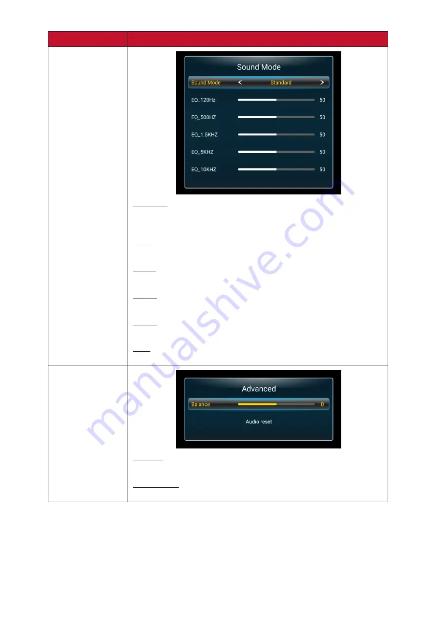
Sound Mode
Standard
Balanced sound quality and effects. Ensures a natural sound
presentation.
News
Reduce the bass and treble, improve voice clarity.
Music
Vibrant treble and stronger bass.
Movie
Enhance the sense of space.
Sports
Enhanced focus on dialogue and speech.
User
Customize the audio equalizer.
Advanced
Balance
Adjust the audio balance from -50~50.
Audio Reset
Restore the settings to default.


