Solar System Design Guide
6020 457 - 01
80
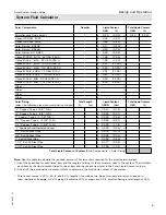
The necessary residual cooling capacity is determined
from the differential between the steam production
capacity of the collector array and the heat dissipation of
the pipework up to the connection point for the expansion
vessel and the heat sink.
For the heat sink, standard radiators with an output
calculated at 207
°
Ra
(
115 K) are assumed. To make
things clearer, the heating output is given as 167/149°F
(75/65°C).
Note:
Viessmann recommends that stagnation coolers be
equipped with a heat shield to provide contact
protection. When using commercially available
radiators, contact protection must be provided. All
system components must be able to withstand
temperatures of up to 356°F (180°C).
Stagnation in Solar Thermal Systems
(continued)
Dimensions
Heat loss in Btuh/ft (W/m)
e
to
b
in. (9.5 to 12.7 mm)
26.0 (25)
c
to 1 in. (19.1/25.4 mm)
31.2 (30)
The pipe run that holds steam during stagnation (steam
spread) is calculated from the balance between the steam
production capacity of the collector array and the heat
losses of the pipe work. For the losses from a solar circuit
pipe made from copper 100% insulated with commercially
available material, the following practical values are
assumed:
■
Steam spread less than the pipe run in the solar circuit
(supply and return) between the collector and the
expansion vessel:
The
steam
cannot
reach the expansion vessel in the
event of stagnation. The displaced volume (collector
array and pipe work filled with steam) must be taken
into account when sizing the expansion vessel.
■
Steam spread greater than the pipe run in the solar
circuit (supply and return) between the collector and
the expansion vessel:
Planning a cooling line (heat sink) to protect the
expansion vessel diaphragm against thermal overload
(see following diagrams). Steam condenses again in
this cooling line and reduces the liquefied heat transfer
medium to a temperature below 158°F (70°C).
Expansion vessel and heat sink in the supply
The steam can propagate only in the supply.
Legend
A
Collector
B
Safety valve
C
Solar-Divicon
D
Heat sink
E
Expansion vessel
Expansion vessel and heat sink in the return
The steam can propagate in the supply and return.
Legend
A
Collector
B
Safety valve
C
Solar-Divicon
D
Heat sink
E
Expansion vessel
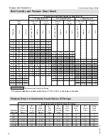
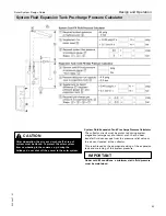
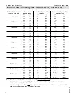
Pressure in solar thermal systems with Vitosol 200-FM
The pressure set for Vitosol 200-FM switching collectors
prevents the formation of steam. Safety cooling devices
for the expansion vessels (stagnation cooler or pre-
cooling vessel) are not required. For calculating the
required pressure, see page 83. If the fluid pressure is
set too low, a small amount of steam can form which
will normally remain in the collectors and not be pushed
into the system. Vitosol 200-FM switching collectors can
therefore be used in systems where the collector array is
below the DHW tank.
Steam-producing power, pressure maintenance and safety
equipment. In the collectors, temperatures are reached
that exceed the boiling point of the heat transfer medium.
For this reason, solar thermal systems must be designed
to be fail-safe in accordance with the relevant regulations.
Design and Operation


