


Installation at the installation site
24
Installation instructions
VITOBLOC 200 EM-530/660
version
SCR
58
41436
GB
PC
PZA+
P
=
50 mbar
T
PZA-
PI
T
max
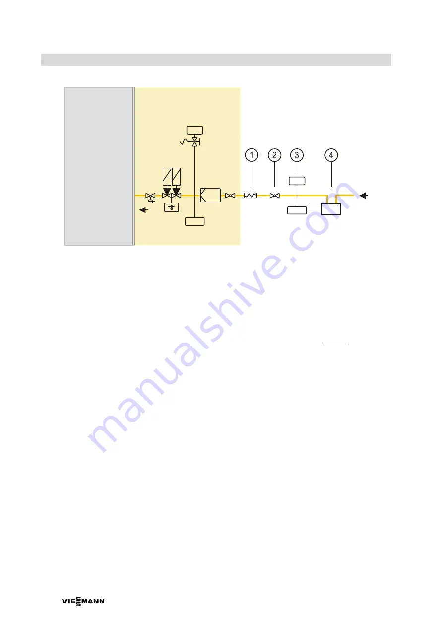
CHP unit
Type-tested gas line
GAS
Z
1
Gas expansion joint (provided loose for on-site installation)
2
Gas ball valve with thermally activated safety valve
3
Pressure control with maximum pressure shutdown (optional equipment
– recommended)
4
Gas meter (optional equipment
– recommended)
Fig. 12
Gas connection diagram
Work on parts carrying gas must be carried out by a
licensed specialist. Devices and components in the
gas supply system must have a DVGW or equivalent
approval in line with the EN standard.
Any alteration to the gas valves in the CHP unit
invalidates the approval and the warranty for any
consequential losses.
Please note!
Do not remove the gas ball valve!
We recommend that the connection lines of the CHP
unit are designed to be larger in order to use this
section as buffer storage. This allows pressure
fluctuations to be absorbed.
The gas quality must meet the manufacturer's
specifications; see appendix section 10.5.
For permissible gas flow pressure, see technical
description for Vitobloc 200 EM-530/660 (versions
SCR and SCR-ready).
If the available gas pressure does not meet
requirements, provide appropriate gas pressure
control equipment on site. The design must take
account of the control times of the gas supply
equipment installed in the CHP unit.
If the gas pressure does not comply with
specifications, then fault-free operation cannot be
guaranteed.
(1) Connect the gas line via the gas expansion joint
(structure-borne noise attenuation) supplied in
the pack.
(2) Fit the gas expansion joint
directly
to the CHP
unit.
(3) Connect the CHP unit to the existing gas supply
via a branch line.
(4) Install a main gas shut-off valve in the CHP unit
branch into the gas supply line.
(5) If the system is intended for mains substitution
mode, the relevant shut-off equipment must be
supplied with 24 V DC voltage (battery
operation!).
(6) Install a gas pressure switch for the maximum
gas pressure in the main line.
(7) The gas lines must be made of suitable
materials.
(8) Provide the gas lines with a RAL colour coating
to DIN 2403 (identifying colour yellow) or with
labels indicating the flow direction.
(9) Perform a tightness test with a corresponding
test report.
(10) We recommend using a calibrated gas meter,
size G100.
(11) Do not attach any pipework to the CHP unit!


