background image

23 

6020930 

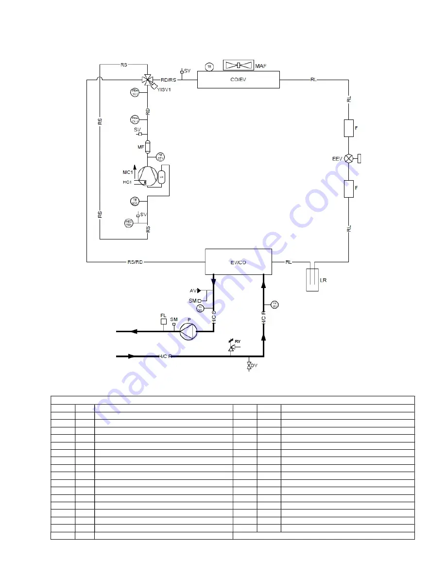
Vitocal 100-A 10 / 12 


KEY 

CODE 

NUM.  DESCRIPTION 

CODE 

NUM. 

DESCRIPTION 

MC


COMPRESSOR 

H/CS


UTILITY WATER OUTLET 

CO/EV 


CONDENSER (IN CHILLER MODE) 

H/CR


UTILITY WATER INLET 

EV/CO 


EVAPORATOR (IN CHILLER MODE) 

PEHTC 

HIGH PRESSURE TRANSDUCER 

EEV 


ELECTRONIC EXPANSION VALVE 

PEDTR 

LOW PRESSURE TRANSDUCER 

YISV 

4-WAY CYCLE REVERSING VALVE 

TE 


OUTDOOR AIR TEMPERATURE PROBE 

LR 


LIQUID RECEIVER 

TE SD 

INTAKE LINE TEMPERATURE PROBE 


FILTER 

TE DT 

COMPRESSOR DISCHARGE TEMPERATURE PROBE 

SV 


FILLING


CONNECTION 

PSHC 

1.1 

AUTOMATIC RESET HIGH-PRESSURE SWITCH 

HC


CRANKCASE HEATER 

TE 

IE


UTILITY INLET TEMPERATURE PROBE 

MAF


AXIAL FAN 

TEOE 

UTILITY OUTLET TEMPERATURE PROBE 

MF


MUFFLER 

DV 


DRAIN


VALVE 

LS


LIQUID SEPARATOR 

RV 


SAFETY VALVE 

RS 


INTAKE LINE 

FL 


FLOW SWITCH 

RD 


DELIVERY LINE 


PUMP 

RL 


LIQUID LINE 

AV 


AUTOMATIC AIR VENTING VALVE 

RD/RS 


DELIVERY/INTAKE LINE 

SM 


SERVICE SLEEVE 

RS/RD 


INTAKE/DELIVERY LINE 


Summary of Contents for AWO-M-AC 101.A06

Page 1: ...1 6020930...

Page 2: ...on the explanations and on the technical specifications provided in this manual Even the partial reproduction of the texts and figures in this manual is prohibited under any form Translation of origin...

Page 3: ...5 ACCESSING THE INNER PARTS 16 5 5 1 Mod Vitocal 100 A 06 08 16 5 5 2 Mod Vitocal 100 A 10 12 17 5 5 3 Mod Vitocal 100 A 14 16 18 5 6 PLUMBING CONNECTIONS 18 5 6 1 Features of the circuit water 19 5...

Page 4: ...LECTRICAL DATA 43 12 OPERATING LIMITS 43 12 1 EVAPORATOR WATER FLOW RATE 43 12 2 COLD WATER PRODUCTION SUMMER MODE 44 12 3 HOT WATER PRODUCTION WINTER MODE 44 12 4 AMBIENT AIR TEMPERATURE AND SUMMARIS...

Page 5: ...refore be considered adequate with respect to the state of the art in terms of potentiality ergonomics safety and functionality The company also performs technological upgrades and does not consider i...

Page 6: ...well as any applicable local laws and specific authorisations All the work must be executed by skilled and qualified personnel competent on the existing regulations in country of installation This ap...

Page 7: ...tors and or damage the unit The operator s workplace has to be kept clean tidy and clear of objects that may hinder free movement Appropriate lighting of the work place shall be provided so as to allo...

Page 8: ...Vitocal 100 A units the following personal protective equipment must be used Clothing Maintenance technicians and operators must wear protective clothing that complies with the basic safety requireme...

Page 9: ...vessels away from the area of the fire if this can be done without posing any risks ACCIDENTAL RELEASE MEASURES Personal precautions Try to stop the leak Evacuate personnel to safety areas Eliminate t...

Page 10: ...effect ENVIRONMENTAL INFORMATION Global warming potential 675 GWP R744 1 Ozone Depletion Potential ODP R11 1 0 Disposal considerations Refer to the supplier s gas retrieval program Avoid direct releas...

Page 11: ...re there are no fire ignition sources near the unit No smoking is allowed near the unit Transport and storage must be performed in accordance with the national regulations in force Specifically accord...

Page 12: ...up the defrost process or for cleaning except for those recommended by the manufacturer The appliance must be placed in a room without ignition sources constantly running for example naked flames a ru...

Page 13: ...normal operation At least 5 m from the appliance there must be no shafts or manholes where gases might build up and generate an explosive atmosphere This is why the Minimum clearances shown below mus...

Page 14: ...the event of winds stronger than 2 2 m s the use of wind barriers is recommended CAUTION It is mandatory to install the unit on a stable base capable of bearing its weight Considering the weight of th...

Page 15: ...15 6020930 5 4 DIMENSIONS 5 4 1 Model Vitocal 100 A 06 08 IN OUT 1 M G E power supply input 5 4 2 Model Vitocal 100 A 10 12 IN OUT 1 M G E power supply input IN OUT OUT IN...

Page 16: ...16 6020930 5 4 3 Model Vitocal 100 A 14 16 IN OUT 1 M G E power supply input 5 5 ACCESSING THE INNER PARTS 5 5 1 Mod Vitocal 100 A 06 08 OUT IN DETAIL A SCALE 1 3 DETAIL B SCALE 1 4 Interlocking tab...

Page 17: ...l B and those on the coil side of the unit To remove the side panel pull it upwards to free the tab at the base indicated as C in detail B and remove it 5 5 2 Mod Vitocal 100 A 10 12 1 Remove the cove...

Page 18: ...water circuit Metal Y filter and dirt separator installed on the return pipe with metal mesh no larger than 1 mm Loading group and exhaust valve where necessary CAUTION when sizing the pipes make sure...

Page 19: ...t water To guarantee correct operation of the unit the water must be appropriately filtered see the instructions at the start of this paragraph and there must be only a minimum amount of dissolved sub...

Page 20: ...ory to connect a drain pipe to this fitting 5 6 5 Filling the system CAUTION supervise all filling top up operations CAUTION before filling topping up the system disconnect power to the units CAUTION...

Page 21: ...eyed to the internal terminals The valve can be kept in a closed position by closing the plug on the drain by loosening the plug the valve remains in open position and air is vented automatically In t...

Page 22: ...TE OUTDOOR AIR TEMPERATURE PROBE LR LIQUID RECEIVER TE SD 1 INTAKE LINE TEMPERATURE PROBE F FILTER TE DT 1 COMPRESSOR DISCHARGE TEMPERATURE PROBE SV FILLING CONNECTION PSHC 1 1 AUTOMATIC RESET HIGH P...

Page 23: ...IR TEMPERATURE PROBE LR LIQUID RECEIVER TE SD 1 INTAKE LINE TEMPERATURE PROBE F FILTER TE DT 1 COMPRESSOR DISCHARGE TEMPERATURE PROBE SV FILLING CONNECTION PSHC 1 1 AUTOMATIC RESET HIGH PRESSURE SWITC...

Page 24: ...R AIR TEMPERATURE PROBE LR LIQUID RECEIVER TE SD 1 INTAKE LINE TEMPERATURE PROBE F FILTER TE DT 1 COMPRESSOR DISCHARGE TEMPERATURE PROBE SV FILLING CONNECTION PSHC 1 1 AUTOMATIC RESET HIGH PRESSURE SW...

Page 25: ...UTION The flow switch element B in the previous plumbing diagram and installed at the factory must ALWAYS be connected according to the indications in the wiring diagram Never jumper the connections o...

Page 26: ...ble from the mains L1 Connect the phase cable L1 from the mains L2 Connect the phase cable L2 from the mains L3 Connect the phase cable L3 from the mains X 5 2 Connection of modbus RTU signal for remo...

Page 27: ...resistive 1A inductive X 16 1 X16 2 Summer winter mode change input from remote to activate the function see the relevant paragraph in the MCO manual Voltage free digital input X 15 1 X15 2 Remote on...

Page 28: ...achine are available Check that the wiring and plumbing diagrams of the plant the machine is connected to are available Check that the shut off valves of the water circuits are open Check that the wat...

Page 29: ...Furthermore power is missing the crankcase heaters will not be powered with the risk of breaking the compressors when the unit is switched on CAUTION Do not modify the electrical connections of the un...

Page 30: ...nd glycol is higher than or at least equal to 5 C 9 MAINTENANCE AND PERIODIC CHECKS CAUTION All the operations described in this chapter MUST BE CARRIED OUT BY QUALIFIED PERSONNEL ONLY Before performi...

Page 31: ...he fans x Correct electric voltage x Correct absorption x Check the refrigerant charge x Check the operating pressure superheating and sub cooling x Circulation pump efficiency x Check the expansion v...

Page 32: ...9 3 ENVIRONMENTAL PROTECTION Legislation regulating the use of substances harmful for the ozone layer establishes the prohibition of releasing refrigerant gases into the environment In fact at the en...

Page 33: ...in the design stage Risk due to Precautions Corrections Handling There is always the risk of the unit falling or tipping over during handling Follow the instructions in the Handling section and take a...

Page 34: ...cognise a flammable atmosphere in time Before during and after the work check the surrounding area for any escaping refrigerant using an explosion proofrefrigerant detector suitable for R32 This refri...

Page 35: ...information Refrigerant lines and components must be installed in such a manner that they do not come into contact with substances that can cause corrosion Exception The refrigerant lines are made fro...

Page 36: ...an affect the function of leak detec tion devices Do not use silicone as a sealant Spare parts must correspond to the manufacturer s specifica tions Work on components which are suitable for flammable...

Page 37: ...t Removal and evacuation When breaking into the refrigerant circuit to make repairs or for any other purpose conventional procedures shall be used However it is important that best practice is followe...

Page 38: ...ent is available if required for handling refrigerant cylinders all personal protective equipment is available and being used correctly the recovery process is supervised at all times by a competent p...

Page 39: ...recovery of flammable refrigerants In addition a set of calibrated weighing scales shall be available and in good working order Hoses shall be complete with leak free disconnect couplings and in good...

Page 40: ...ary Twin Rotary Twin Rotary DC Inverter DC Inverter DC Inverter DC Inverter Refrigerant oil type ESTEL OIL RB74AF ESTEL OIL RB74AF ESTEL OIL VG74 ESTEL OIL VG74 Number of compressors 1 1 1 1 Oil charg...

Page 41: ...ter temperature 23 18 C 3 Heating outdoor air temperature 7 C db 6 C db in out water temp 30 35 C 4 Heating outdoor air temperature 7 C db 6 C db in out water temp 40 45 C 5 Cooling in out water tempe...

Page 42: ...y DC Inverter DC Inverter DC Inverter DC Inverter Refrigerant oil type ESTEL OIL VG74 ESTEL OIL VG74 ESTEL OIL VG74 ESTEL OIL VG74 Number of compressors 1 1 1 1 Oil charge amount L 1 4 1 4 1 4 1 4 Ref...

Page 43: ...wer according to EN 14511 The value declared in point 5 and 6 is determined according to UNI EN 14825 CAUTION The minimum temperature allowed for storing the units is 5 C 11 2 UNIT AND AUXILIARY ELECT...

Page 44: ...and assess the changes to be made according to demands A maximum temperature of 25 C can be maintained at the evaporator outlet in steady state operation 12 3 HOT WATER PRODUCTION WINTER MODE When the...

Page 45: ...et water temperature Minimum 25 C Maximum 60 C Heat pump mode for domestic hot water Room temperature with water at maximum 39 C Minimum 20 C Maximum 40 C Room temperature with water at maximum 55 C M...

Page 46: ...46 6020930 CHILLER MODE DOMESTIC HOT WATER MODE DHW mode Cooling...

Page 47: ...y valve on Defrost LED ON if defrosting enabled OFF if defrosting disabled or finished FLASHING if defrosting time interval count in progress Antifreeze heater LED LED ON if antifreeze heater on Pump...

Page 48: ...le if connected to Hi t2 Probes tP Installer Alarms Err User Only if active alarms Digital inputs Id Installer Parameters Par Installer Password PSS User Hours of operation oHr Installer USB USb Insta...

Page 49: ...49 6020930...

Page 50: ...50 6020930...

Page 51: ...51 6020930...

Page 52: ...52 6020930...

Reviews: