Vicon Andex 844 Assembly Instructions Manual Download Page 20

Crate packaging

20

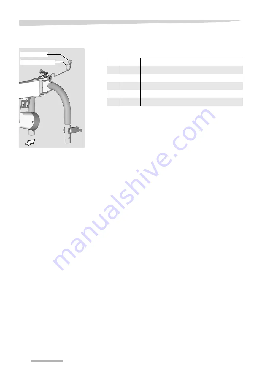
Fitting the hose guide

Fit the hose guide and cable guide to the attachment carrier.

Hose guide

Cable guide

No.

Quantity

Part

1

1

Hose guide and cable guide

2

1

Perforated plate

3

2

M 10 x 30 mushroom head bolts

4

2

11 x 20 x 2 washers

5

2

Self-locking nuts

Summary of Contents for Andex 844

Page 1: ...Andex 844 Assembly instructions Original assembly instructions Edition 10 2012 Date of print 10 2012 Language EN Machine number VF65882401 Model VF6588 Document number VF16649595 EN ...

Page 2: ...up Gottmadingen N V Germany Reproduction transfer to other media translation or the use of extracts or parts of this manual without the explicit permission of Kverneland is not permitted All rights reserved The contents of this operating manual are subject to change without notice The right to technical revision is reserved ...

Page 3: ... electrics 33 Swath former 36 Parking stands 40 Rotor 41 Drive 45 Protective equipment 46 Fitting the balance spring 49 Final assembly with crate packaging 50 Pallet packaging 51 Requirements 51 Pallet assembly 52 Hydraulics 55 Fitting the rotor chassis 56 Final assembly with pallet packaging 59 Setting up work 60 Length of the PTO shaft 60 Steering 62 Fitting the tine supports 63 Adjusting the ro...

Page 4: ...Table of contents 4 ...

Page 5: ...ployer Untrained or unauthorised individuals are not permitted to assemble the machinery Meaning of the symbols In these assembly instructions the following symbols and terms have been used A bullet point accompanies each item in a list A triangle indicates operating functions which must be performed We have also used pictograms to help you find instructions more quickly The Information pictogram ...

Page 6: ...ons All personnel involved in the assembly must be aware of these rules and regulations and adhere to them they must also be instructed on the potential risks and dangers Unauthorised alterations to the machine invalidate any liability of the manufacturer for resultant damage The following rules and regulations must be observed The locally applicable accident prevention regulations The recognised ...

Page 7: ... Wear sturdy footwear and prescribed protective equipment Support and secure the machine carefully during assembly Particular care must be taken in dealing with energy accumulators such as springs and hydraulic or compressed air assemblies Dispose of oils grease and filters in accordance with regulations Protective equipment must be properly attached and swung into its protective position Actuatio...

Page 8: ...o bottom Rotation about a horizontal axis viewed at right angles to the direction of travel from left to right The rotation of screws and nuts etc is always viewed from the operating side 8 8 10 9 12 9 M 6 9 9 Nm 7 3 ft lbs 14 Nm 10 3 ft lbs 17 Nm 12 5 ft lbs M 8 24 Nm 17 7 ft lbs 34 Nm 25 ft lbs 41 Nm 30 3 ft lbs M 10 48 Nm 35 4 ft lbs 68 Nm 50 2 ft lbs 81 Nm 59 8 ft lbs M 12 85 Nm 62 7 ft lbs 12...

Page 9: ...nents Deflector bar Main frame Attachment carrier Deflector bar Drive Tine support Tines Swath former Rotor gear Transport chassis Rotor chassis Transport holder for tine supports Sustainer Steering Rotor arm shaft Telescopic arm Lifting arm ...

Page 10: ...Overview 10 Small parts Control cables Lighting cable Gear box assembly material Deflector bar assembly material Main frame assembly material Lynch pins ...

Page 11: ...nsole Attachment carrier Hydraulic cylinder No Assembly group Page 1 Fitting the attachment carrier 14 2 Connecting the main frame to the transport chassis 16 3 Connecting the front main frame to the rear main frame 18 4 Fitting the left and right lifting arms to the lifting arm console 26 5 Fitting the bearing housing to the rotor 43 6 Fitting the rotor to the lifting arm 44 7 Fitting the side sh...

Page 12: ...rm Front main frame Side shaft Left lifting arm Wheel Wheel hub Rotor chassis No Assembly group Page 1 Connecting the front main frame to the rear main frame 18 2 Fitting the wheels onto the transport chassis 16 3 Fitting the rotor chassis onto the rotor gear 56 4 Fitting the side shafts 45 ...

Page 13: ... REPORT MISSING PARTS form and send it to the ORDER DESK in Kerteminde straight away Removing the surface protection Remove the surface protection e g Tectyl with which the bare surfaces such as tine arms tine supports and bearing shafts have been coated Grease the bare surfaces using a brush Observe the safety information Observe the safety information when carrying out all work Disregard for saf...

Page 14: ... all fastenings wires lashing straps Fitting the attachment carrier Fit the attachment carrier to the main frame To do this proceed as follows Place the front main frame securely on stands Using suitable lifting gear bring the attachment carrier to the front main frame Insert the pin and secure it using dowel pins ...

Page 15: ...Crate packaging 15 Attachment carrier assembly drawing Drive in the dowel pins at 90 to each other Pin Dowel pins Attachment carrier Front main frame ...

Page 16: ...adjust them and screw into place Fit the wheel hub onto the axles Fit the wheels of the transport chassis onto the axles Attach the protective cap Rear main frame Transport chassis Steering arm Axle No Quantity Part 1 1 Transport chassis 2 6 M 16 x 140 bolts 3 12 M 16 nuts 4 18 M 16 washers 5 2 Axles 6 2 10 0 75 15 3 wheels 7 2 Steering arm 8 2 M 16 x 80 bolts 9 2 Spacer sleeves 10 2 Wheel chocks ...

Page 17: ...sis assembly drawing Dowel pins Wheel chock M 18 x 1 5 wheel nuts 270 Nm M 16 x 140 M 16 x 80 Spacer sleeve Spacer sleeve Drive in the dowel pins at 90 to each other Reflector 35 cm above driving surface M 16 x 120 290 Nm 290 Nm 290 Nm ...

Page 18: ... frame Then connect to the existing assembly cable and pull through the rear frame Remove the hydraulic line ball valves Pull the hydraulic lines from the rear through the front main frame Fit the hydraulic line ball valves Guide both frame parts together at the flange pieces Using 4 bolts loosely connect the flange pieces from the front and rear main frames Secure the flange pieces using 2 clampi...

Page 19: ...aulic lines 1 electrical line Front main frame Bolts and washers 290 Nm Tine cover holder Rear main frame First thread the electrical lines lighting cables from the front to the rear through the front main frame Then connect to the existing assembly cable and pull through the rear frame ...

Page 20: ...guide Fit the hose guide and cable guide to the attachment carrier Hose guide Cable guide No Quantity Part 1 1 Hose guide and cable guide 2 1 Perforated plate 3 2 M 10 x 30 mushroom head bolts 4 2 11 x 20 x 2 washers 5 2 Self locking nuts ...

Page 21: ... the steering rods page 24 The lock nut for the front steering rod is secured in place at the factory and must not be loosened When adjusting the steering only correct the length of the rear steering rod Front steering rod Rear steering rod Swinging arm Right steering rod Left steering rod Bearing shell Secured lock nut Do not loosen The holes of the steering rods must be aligned vertically to the...

Page 22: ...pin through the swinging arm and secure with self locking nut max 50 Nm Use a grease gun to grease all of the pins Right steering rod Left steering rod No Quantity Part 1 1 Right steering rod 2 1 Left steering rod 3 1 Locking plate 4 1 M 8 x 20 bolt 5 1 M 8 self locking nut 6 2 Threaded pins with lubricating nipple 7 2 M 16 self locking nuts Right steering rod Left steering rod Threaded pin Lockin...

Page 23: ...g rod respectively to the left and right lever on the transport chassis and align Insert the threaded pin through the swinging arm and secure with self locking nut max 50 Nm Use a grease gun to grease all of the pins Right steering rod Left steering rod Lever No Quantity Part 1 1 Right steering rod 2 1 Left steering rod 3 2 Threaded pins with lubricating nipple 4 2 M 16 self locking nuts Left stee...

Page 24: ...at the factory When adjusting the steering only correct the length of the rear steering rod Pay close attention to the alignment of the holes of the steering rods The holes of the steering rods must be aligned vertically to the ground and parallel to each other After adjusting the steering secure the steering rod with the lock nut Clevis Front steering rod Bearing shell Rear steering rod No Quanti...

Page 25: ...ms with hydraulics and the transport locking bars for both rotors to the main frame Secure the lift arms and the hydraulic cylinders using suitable lifting accessories Left lifting arm Right lifting arm Flange bearing Lifting arm console Bearing shaft ...

Page 26: ...hims to evenly adjust the seating of the lift arm so that with the flange bearings a value of a 1 mm is reached Use a brush to grease the flange pieces and lifting arm supports Fit the dowel pins Insert M 8 bolts Fit the moulded washers in the correct position Shim Flange bearing Lifting arm Lifting arm support Shim Flange bearing Supporting disc Shim Shim Flange bearing Lifting arm Lifting arm co...

Page 27: ...Quantity Part 1 2 Lifting arms 2 4 Flange piece 3 4 50 x 62 x 1 shims 4 4 50 x 62 x 3 supporting discs 5 16 M 12 x 50 bolts 8 M 8 x 50 bolts 6 16 M 12 washers 8 M 8 washers 7 16 M 12 self locking nuts 8 8 M 8 self locking nuts 9 4 Moulded washers 8 13 x 36 dowel pins 120 Nm M 12 bolt ...

Page 28: ...miters When doing so make sure that the lift limiters do not jam Secure bolts with dowel pins Hook the spring to the lift arm console and the lift arm limiter Bush Lift limiter Hydraulic cylinder Pin Dowel pin Bush with holder Spring Lifting arm console Dowel pin No Quantity Part 1 2 Lift limiter 2 2 Hydraulic cylinder 3 2 Pin 4 4 10 x 50 dowel pins 5 2 Bushes 6 2 Bushes with holder 7 2 Springs ...

Page 29: ...to the hydraulic cylinder page 70 Grease the pins with a brush Fit the piston rod to the mounting point Mounting point for piston rod Piston rod Fixing eyelet No Quantity Part 1 2 Hydraulic cylinder 2 2 Pin 3 4 31 x 45 x 2 washers 4 4 38 x 27 x 3 6 distance pieces 5 4 6 x 50 dowel pins Washer Fixing eyelet Pin Distance piece Dowel pin Dowel pin Mounting point for piston rod Piston rod Hydraulic cy...

Page 30: ...l Observe the labelling of the hydraulic hoses See Raising the lifting arms page 31 See Telescoping the lifting arms page 31 See Electrohydraulic single lift page 32 Please note the instructions for commissioning in the Final operations chapter and the Introducing air to the hydraulic cylinder instructions from page 70 Cable tie Lifting arm Main frame Chain links Scouring protection coil ...

Page 31: ...cting hydraulic control unit Telescoping the lifting arms Plan overview for connecting to tractor s double acting hydraulic control unit Hydraulic cylinder Ball valve Hydraulic cylinder for swath former Master hydraulic cylinder Ball valve Marked in yellow Marked in red Slave hydraulic cylinder ...

Page 32: ...ackaging 32 Electrohydraulic single lift Connection to solenoid valves and pilotbox control and tractor s single acting hydraulic control unit For assembly see Fitting the electrohydraulic single lift page 65 ...

Page 33: ...to the keyhole on the main frame with bolts and allow to lock into place at the bottom Align the warning sign correctly and tighten the nuts Lay the lighting cable See Laying the lighting cables for the lighting equipment page 34 No Quantity Part 1 2 Warning sign and lighting equipment set Illuminated warning signs Transport chassis Keyhole Rear view ...

Page 34: ... ties to fix the lighting cable to the lashing eyelets on the transport chassis Connect the short and long lighting cables Ensure the correct position of the plug and bush Stow cable connections in the cable duct under the main frame No Quantity Part 1 1 Lighting cable set with cable ties Long lighting cable in main frame Lighting equipment Short lighting cable on transport chassis Lashing eyelets...

Page 35: ...l cables as illustrated and secure using cable stoppers See Control cable page 39 Fit the scouring protection coil Ensure that there is sufficient free space The lighting cable and the hydraulic hoses must not chafe or be clamped during movement and cornering Cable tie Ceramic eyelet Rope stopper Control cable 3 pin plug Ball valve Scouring protection coil Scouring protection coil ...

Page 36: ...r the swath former are fitted to the swath former holder No Quantity Part 1 1 Pre assembled swath former 2 2 Pre assembled control arm 3 1 Hydraulic cylinder 4 1 Spring Swath former Hydraulic cylinder Control arm with hydraulic cylinder Control arm with spring Front main frame Rear main frame Spring ...

Page 37: ... frame using pins and washers Connect the piston rod pin to the rear control arm Secure the piston rod pin with a split pin No Quantity Part 1 2 Pre assembled control arm 2 2 11 x 142 pins 3 6 17 x 28 x 3 washers 4 6 5 x 32 split pins 5 1 Hydraulic cylinder 6 1 Spring Front control arm Hydraulic cylinder Rear control arm Spring Piston rod Support for swath former Support for main frame ...

Page 38: ... spacer tube Fit the swath former in the hole pattern shown below and screw tight No Quantity Part 1 1 Pre assembled swath former 2 2 Pre assembled control arm 2 M 10 x 135 bolts 3 4 M 10 washers 4 2 M 10 self locking nuts Swath former Spacer tube Self locking nut and washer Control arm Bolt and washer Swath former 705 mm ...

Page 39: ...Lay the control cables as illustrated Guide the control cables through the ceramic eyelet on the attachment carrier Push the rope stopper on to the control cable and secure the knots Secure the control cables with the rope stopper so that they are slightly tensioned when the lifting arm is lowered Hydraulic cylinder T piece Ceramic eyelet Rope stopper Control cable Knots No Quantity Part 1 2 Contr...

Page 40: ...orts beneath the main frame and beneath the transport chassis When fitting the parking stands make sure that they are parallel Parking stands No Quantity Part 1 2 Parking stands for tine supports 2 4 M 12 x 35 bolts 3 4 M 12 washers 4 4 M 12 self locking nuts Self locking nuts Washer Bolt Parking stands ...

Page 41: ...ng 41 Rotor Fitting the rotor The rotor gears are pre fitted on the rotor chassis No Quantity Part 1 2 Pre assembled rotor chassis with rotor gear 2 8 16 x 6 5 wheels 3 8 Cover caps 20 Nm wheel nut Wheel Rotor gear ...

Page 42: ...ch on all wheel carriers in advance See Adjusting the rotor pitch page 64 Fitting the double wheel Fit double wheels to both rotor chassis Tighten the wheel nuts on the wheels to 20 Nm Fit the wheel caps to the wheels Wheel Double wheel Left rotor Wheel carrier 20 Nm 20 Nm Observe the Left sticker Double wheel Outer wheel cap Wheel nut Washer Inner wheel cap Wheel Cover 20 Nm ...

Page 43: ...nto the correct position using suitable loading accessories Slide the rotor into the correct position Tightly screw the bearing housing to the rotor 290 Nm Rotor Bearing housing M 16 x 55 coated bolts Sleeves Observe the Left sticker No Quantity Part 1 2 Bearing housing preassembled 2 2 Assembled rotor 3 8 M 16 x 55 coated bolts 4 8 30 x 6 x 15 sleeves ...

Page 44: ...the correct position Use a brush to grease the lift arm bearing shaft Slide the rotor with the bearing housing into the correct position Align the lift arm bearing shaft using shim discs Secure the bearing shaft with a ring Secure the ring with a dowel pin Shim Bearing housing Bearing shaft Shim Ring Dowel pin Lifting arm ...

Page 45: ...brush to grease the PTO stub shafts Place the side shaft onto the gear box and allow to lock into place Fit the side shaft onto the rotor gear and secure with a bolt Greasing schedule for PTO shafts No Quantity Part 1 2 Side shafts No Quantity Part 1 1 WWE 2280 drive shaft 2 2 W 2200 side shaft for left and right rotors 3 1 Gear box Coupling ...

Page 46: ...1 2 Deflector carrier 2 8 M 12 x 35 bolts 3 12 M 12 self locking nuts 4 12 M 12 washers 2 Clamp for crank locking device 6 2 Retainer plates 7 4 M 12 x 55 bolts 8 2 Deflector bar 9 2 Springs 10 4 31 x 45 x 2 washers 11 4 Split pins Bearing housing Deflector carrier Deflector bar Left rotor Retainer plate ...

Page 47: ...ecure with a dowel pin Fit the retainer plate onto the deflector carrier Fitting the crank Place the crank on each rotor onto the flexible shaft and secure using dowel pins Fit the crank locking device to the support on the deflector carrier Flexible shaft Left gear box Retainer plate Deflector carrier Bearing housing Crank locking device Crank No Quantity Part 1 2 Cranks 2 2 Crank locking device ...

Page 48: ...ar opening on the deflector carrier Push the deflector bar into the front opening Slide on washer at the front and secure with split pin On the rear part of the deflector bar first push on the spring and then the washer Secure the washer with the split pin No Quantity Part 1 2 Deflector bar 2 2 Springs 3 4 Split pins 4 4 31 x 45 washers Split pin Deflector bar Washer Washer Spring Split pin Deflec...

Page 49: ...support on the rotor Hook the eye bolt to the spring and place it through the hole Tighten the eye bolt Adjustment 50 mm distance from stopper to the end of the eye bolt Effect of the eye bolt Balance spring No Quantity Part 1 2 Balance spring 2 2 Eye bolt M 12 x 90 3 2 M 12 nut Balance spring Eye bolt Left rotor 50 mm ...

Page 50: ...Crate packaging 50 Final assembly with crate packaging Proceed as follows to complete the assembly Setting up work see page 60 Accessories see page 65 Final operations see page 70 ...

Page 51: ...rm and send it to the ORDER DESK in Kerteminde straight away Removing the surface protection Remove the surface protection e g Tectyl with which the bare surfaces such as tine arms tine supports and bearing shafts have been coated Grease the bare surfaces using a brush Observe the safety information Observe the safety information when carrying out all work Disregard for safety information can lead...

Page 52: ...ical lines through the openings in the flange pieces of the two main frames Raise the rear main frame with lifting accessories and secure under the flange piece with stand Raise the front main frame with lifting accessories and secure The long lighting cable is preassembled on the rear main frame Using the assembly cable pull the long lighting cable through the front main frame Remove the hydrauli...

Page 53: ...aining bolts Connect the flange pieces using 12 bolts torsion free Rear main frame Front main frame Clamping sleeve No Quantity Part 1 1 Rear main frame 2 1 Front main frame 3 12 M 16 x 60 bolts 4 12 M 16 nuts 5 24 M 16 washers 6 2 21 x 26 clamping sleeves Clamping sleeve Nuts and washers 3 hydraulic lines 1 electrical line Front main frame Rear main frame Bolts and washers 290 Nm ...

Page 54: ...essories and secure Use a brush to grease the bushes of the wheel hub Fit the wheel hub onto the axles Fit the wheels of the transport chassis onto the axles Transport chassis Axle Wheel hub No Quantity Part 1 1 Transport chassis 2 4 M 16 x 120 bolts 3 4 M 16 nuts 4 8 M 16 washers 5 2 Wheel hubs 6 2 10 0 75 15 3 wheels ...

Page 55: ...the machine to the tractor Do not couple the PTO shaft Connect the machine hydraulics to the tractor Position the main frame horizontally with the tractor s power lever Please note the instructions for commissioning in the Final operations chapter and the Introducing air to the hydraulic cylinder instructions from page 70 ...

Page 56: ...it the wheels onto both rotor chassis See Fitting the wheels page 42 Use the tractor s hydraulic control unit to fold back the lift arms until the underside of the rotor gears is approx 70 cm above the ground Switch off the tractor and secure it Close the ball valve Main frame Lifting arm Rotor Rotor chassis Left sticker ...

Page 57: ...le shaft Use a brush to grease the profile shaft thread and the spindle Carefully position the spindle on the rotor gear onto the rotor chassis and screw it at least 5 turns into the profile shaft of the rotor chassis Lift the rotor until the spindle ball bearing sits firmly in the rotor gear Secure the ball bearing with a circlip Fit the shaft sealing ring Rotor chassis Rotor gear Adjusting screw...

Page 58: ...event the spindle turning out from the rear The gap between the self locking nut and the hexagonal profile is around 5 mm Use the tractor s hydraulic control unit to completely fold back the lift arms Switch off the tractor and secure it Close the ball valve Gaiter Adjusting screw for tine lifting Adjusting screw for tine lifting 5 mm Self locking nuts Hexagonal profile ...

Page 59: ... page 21 Lifting arms see page 25 Laying the hydraulic lines see page 30 Swath former see page 36 Drive see page 45 Lighting equipment and electrics see page 33 Protective equipment see page 46 Fitting the balance spring see page 49 Setting up work from page 60 Accessories see page 65 Final operations see page 70 ...

Page 60: ...Lower the lower link of the tractor Set the combination tractor and machine to the smallest steering angle Switch off the tractor and secure it against rolling away Switching off the tractor and securing it Before you dismount Switch off the tractor Remove the ignition key Secure the tractor against rolling away An unsecured tractor can run you over or trap you Serious or fatal injury would be cau...

Page 61: ...ne end minimum distance a 20 mm Shorten the slide tube and guard tube by the same dimension Deburr the ends of the tube Remove the swarf Grease the sliding surfaces well Fitting the PTO shaft Make sure that you fit the PTO shaft in the correct installation position There is a marking on the guard tube of the PTO shaft Check the length of the PTO shaft and shorten it if necessary Place the PTO shaf...

Page 62: ... stability is set incorrectly Proceed as follows Switch off the tractor and secure it Control length of the front steering rod L1 approx 2 464 mm Control length of the rear steering rod L2 approx 2 612 mm Check lengths S of the track rods S 1 015 mm Check track A at the front and rear sides of the tyres Front A Rear A 3 mm Track arm Steering arm Track rod Steering rod Front steering rod L1 2 464 m...

Page 63: ...t Secure the lynch pin in the rear hole of the tine support Fit the tine supports Secure the tine supports with lynch pins The tine supports for the left rotor are labelled The tine supports for the right rotor are not labelled Lynch pins Rear hole Tine support Tine support for the left rotor Label ...

Page 64: ...s laterally to the direction of travel Undo the four bolts on the wheel carrier slightly Push the wheel carriers into the required position see graphic below Retighten the bolts 4 x M 12 bolts to 85 Nm 20 mm 20 mm Tines Crop pickup increases the distance between the tines and the ground 0 mm 0 mm ...

Page 65: ...to the lift arm console Lay the hydraulic hoses and connect according to the hydraulic diagram Use cable ties to fix the control box cable to the main frame Hydraulic block holder Hydraulic block Electrical plug Solenoid valve Preselection Function Pilotbox OFF Raise and lower both rotors Pilotbox ON Control LED lights up The A and C functions are available A Raise and lower the left rotor Connect...

Page 66: ...Accessories 66 Ball valve Control box Hydraulic block Electrical plug Hydraulic block holder C A B Solenoid valve Lifting arm console ...

Page 67: ...osition Check the tine position for each tine If the tine saver is overtightened the tine legs become splayed Check the tine position Loosen the screwed connection until both tine legs run parallel Tandem axles The optional tandem axles provide better contour guidance The tandem axles replace the rear running wheels Separate assembly instructions are supplied Fit the tandem axle so that the wide t...

Page 68: ... Circuit diagrams Hydraulics circuit diagram l Left lifting arm Tractor hydraulics Lift arm extension Electrohydraulic single lift Restrictor 0 5 mm Right lifting arm Swath former Restrictor 1 5 mm Restrictor 1 5 mm Y1 Y3 ...

Page 69: ...rown Red Black Right indicator Right brake light Right rear light Right side light Yellow White Red Brown Black White Left side light White Black Black Connectors and sockets 7 pin in accordance with ISO 1724 Left rear light Left indicator Left brake light Earth Connecting plug 7 pin in accordance with ISO 1724 ...

Page 70: ...TO shaft Connect the machine hydraulics to the tractor Position the main frame horizontally with the tractor s power lever Use the tractor s hydraulic control unit to fold back the lift arms Switch off the tractor and secure it Close the ball valve Remove the valve cap on the lifting arm hydraulic cylinders Press against the valve with the valve cap until air can no longer be heard flowing in Clos...

Page 71: ...les Hydraulic connections based on the components Extend and retract the hydraulic cylinders from the end position at least 10 times in order to bleed the cylinders Once complete check the hydraulic system for leaks Environment Dispose of packaging according to the current local waste disposal guidelines Ensure that lubricants are handled and disposed of correctly No persons within the slewing ran...

Reviews: