


7
Names and functions of parts
This section covers the names and functions of parts in the driver and motor.
Note
• Even when the motor is stopped, the current remains on and the motor continues to
generate heat.
• While the motor is in the stopped state, the current is automatically reduced to a value
preset by the motor-stop current-adjustment control (STOP) to limit the generation of
heat. The motor’s holding torque is also reduced in proportion to the stopped-state
current. Adjust the motor-stop current-adjustment control (STOP) setting to ensure the
necessary load-holding torque.
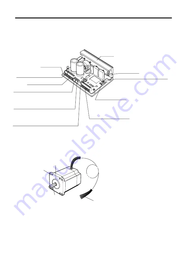
Motor
Illustration typical for the
PK56
and
PK59
.
VEXTA
DA
10
XL1 C.C.
SW
3
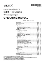
Mounting holes
Power-supply terminal block (TB1)
Motor terminal block (TB2)
Motor-run current-adjustment control (RUN)
Motor-stop current-adjustment control (STOP)
Step-angle setting switches (DATA1, DATA2)
Sets the current for when the motor is running.
The factory setting is the motor’s rated
current (2.8 A/phase).
Sets the current for when the motor is stopped.
The factory setting is about 50%
of the motor’s rated current.
DATA1 and DATA2 each set one of 16 step angles.
DATA1 and DATA2 are select with the C/S (step-angle switching) input.
The factory setting is [0: 0.72˚] for both DATA1 and DATA2.
Mounting cutout
Pulse input mode selector switch (1P/2P)
DC check switch (C.C.)
Heat sink
Switches between 1-pulse input mode
and 2-pulse input mode.
The factory setting is 1P: 1-pulse input mode.
Switch used when adjusting the motor’s running current.
When running the motor, always have this switch set to OFF.
The factory setting is OFF.
I/O signal terminal block (TB3)
Pilot
Output shaft
Mounting holes
(4 locations)
Motor leads
(5 wires: blue, red, orange, green and black)
Driver
Illustration shows the
DFC5128T
.


