5.
L
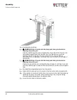
WARNING! Risk of crush injuries to hands when closing the locking
device!
Close the locking device of the fork arms. When doing so, ensure your fingers
are not in the danger zone and flip the lever again using appropriate force.
6.
Check that the fork arms are locked into the locking groove (Fig. 10/2). If this is
not the case, move the fork arms horizontally until the lock engages.
Shaft fork arm locking device
Depending on the operator's requirements and intended use, shaft fork arms are sup-
plied as follows: either freely movable on the shaft, using adjusting rings on both sides
of the two shaft fork arms, or with a locking screw on the shaft.
1.
Raise the fork arms up from the ground.
2.
If installed, loosen the locking device (adjusting rings or locking screw in the
shaft) of the shaft fork arms.
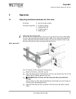
Fig. 11: Shaft fork arm spacing
3.
L
WARNING! Risk of hands and other body parts being crushed when
moving!
Grip the fork arms at the head and fork blade and carefully move it to the side on
the fork carrier with appropriate force (Fig. 11).
4.
Align both fork arms evenly to the center of the fork carrier and at the required
width.
Shaft suspension
Operation
Adjusting the distance between the fork arms
Fork carrier with fork arms
28
Summary of Contents for ManuTel
Page 2: ...Fork carrier with fork arms 2 ...
Page 52: ......


