27
Plasma TV Service Manual
05/01/2006
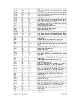
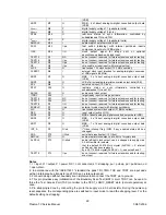
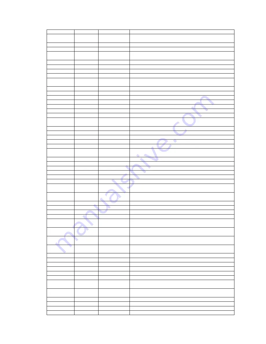
83H)
TEST4
B12
O
do not connect, reserved for future extensions and for testing:
scan output
TEST5
B13
NC
do not connect, reserved for future extensions and for testing
TEST6
B14
NC
do not connect, reserved for future extensions and for testing
VSSA4
C1
P
ground for analog inputs AI4x
AGND
C2
P
analog ground
TEST7
C3
NC
do not connect, reserved for future extensions and for testing
TEST8
C4
NC
do not connect, reserved for future extensions and for testing
V
DDD1
C5
P
digital supply voltage 1 (peripheral cells)
TRST
C6
I/pu
test reset input (active LOW), for boundary scan test (with
internal pull-up); notes 2, 3 and 4
XRH
C7
I/O
horizontal reference I/O expansion port
V
DDD2
C8
P
digital supply voltage 2 (core)
V
DDD3
C9
P
digital supply voltage 3 (peripheral cells)
V
DDD4
C10
P
digital supply voltage 4 (core)
XPD7
C11
I/O
MSB of expansion port data
TEST9
C12
NC
do not connect, reserved for future extensions and for testing
TEST10
C13
NC
do not connect, reserved for future extensions and for testing
TEST11
C14
I/pu
do not connect, reserved for future extensions and for testing:
scan input
AI43
D1
I
analog input 43
AI42
D2
I
analog input 42
AI4D
D3
I
differential input for ADC channel 4 (pins AI41 to AI44)
V
DDA4
D4
P
analog supply voltage for analog inputs AI4x (3.3 V)
V
SSD1
D5
P
digital ground 1 (peripheral cells)
TMS
D6
I/pu
test mode select input for boundary scan test or scan test;
note 2
V
SSD2
D7
P
digital ground 2 (core; substrate connection)
XRV
D8
I/O
vertical reference I/O expansion port
V
SSD3
D9
P
digital ground 3 (peripheral cells)
V
SSD4
D10
P
digital ground 4 (core)
V
SSD5
D11
P
digital ground 5 (peripheral cells)
V
DDD5
D12
P
digital supply voltage 5 (peripheral cells)
TEST12
D13
I/pu
do not connect, reserved for future extensions and for testing:
scan input
HPD0
D14
I/O
LSB of host port data I/O, extended C
B
-C
R
input for
expansion port, extended C
B
-C
R
output for image port
AI44
E1
I
analog input 44
V
DDA4A
E2
P
analog supply voltage for analog inputs AI4x (3.3 V)
AI31
E3
I
analog input 31
V
SSA3
E4
P
ground for analog inputs AI3x
HPD1
E11
I/O
MSB - 6 of host port data I/O, extended C
B
-C
R
input for
expansion port, extended C
B
-C
R
output for image port
HPD3
E12
I/O
MSB - 4 of host port data I/O, extended C
B
-C
R
input for
expansion port, extended C
B
-C
R
output for image port
HPD2
E13
I/O
MSB - 5 of host port data I/O, extended C
B
-C
R
input for
expansion port, extended C
B
-C
R
output for image port
HPD4
E14
I/O
MSB - 3 of host port data I/O, extended C
B
-C
R
input for
expansion port, extended C
B
-C
R
output for image port
AI3D
F1
I/O
differential input for ADC channel 3 (pins AI31 to AI34)
AI32
F2
I
analog input 32
AI33
F3
I
analog input 33
V
DDA3
F4
P
analog supply voltage for analog inputs AI3x (3.3 V)
V
SSD6
F11
P
digital ground 6 (core)
V
DDD6
F12
P
digital supply voltage 6 (core)
HPD5
F13
I/O
MSB - 2 of host port data I/O, extended C
B
-C
R
input for
expansion port, extended C
B
-C
R
output for image port
HPD6
F14
I/O
MSB - 1 of host port data I/O, extended C
B
-C
R
input for
expansion port, extended C
B
-C
R
output for image port
AI34
G1
I
analog input 34
V
DDA3A
G2
P
analog supply voltage for analog inputs AI3x (3.3 V)
AI22
G3
I
analog input 22
AI21
G4
I
analog input 21
Summary of Contents for 17MB11
Page 1: ...50 PLASMA TV 17MB11 SERVICE MANUAL...
Page 50: ...47 Plasma TV Service Manual 25 08 2005 15 CIRCUIT DIAGRAMS...
Page 51: ...48 Plasma TV Service Manual 25 08 2005...
Page 52: ...49 Plasma TV Service Manual 25 08 2005...
Page 53: ...50 Plasma TV Service Manual 25 08 2005...
Page 54: ...51 Plasma TV Service Manual 25 08 2005...
Page 55: ...52 Plasma TV Service Manual 25 08 2005...
Page 56: ...53 Plasma TV Service Manual 25 08 2005...
Page 57: ...54 Plasma TV Service Manual 25 08 2005...


