background image

26 

Plasma TV Service Manual 


05/01/2006


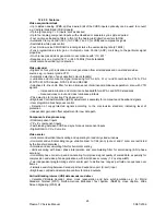
Audio clock generation 

• Generation of a field-locked audio master clock to support a constant number of audio clocks per 
video field 
• Generation of an audio serial and left/right (channel) 
 

Digital I/O interfaces 

• Real-time signal port (R port), inclusive continuous line-locked reference clock and real-time status 
information supporting RTC level 3.1 (refer to document “RTC Functional Specification” for details) 
• Bidirectional expansion port (X-port) with half duplex functionality (D1), 8-bit Y-C

B

 -C

R


– Output from decoder part, real-time and unscaled 
– Input to scaler part, e.g. video from MPEG decoder (extension to 16-bit possible) 
• Video image port (I-port) configurable for 8-bit data (extension to 16-bit possible) in master mode (own 
clock), or slave mode (external clock), with auxiliary timing and handshake signals 
• Discontinuous data streams supported 
• 32-word ´ 4-byte FIFO register for video output data 
• 28-word ´ 4-byte FIFO register for decoded VBI-data output 
• Scaled 4 :2 :2, 4 :1 :1, 4 :2 :0, 4 :1 :0 Y-C

B

 -C

R

 output 

• Scaled 8-bit luminance only and raw CVBS data output 
• Sliced, decoded VBI-data output. 
 

Miscellaneous 

• Power-on control 
• 5 V tolerant digital inputs and I/O ports 
• Software controlled power saving standby modes supported 
• Programming via serial I 2 C-bus, full read back ability by an external controller, bit rate up to 400 
kbits/s 
• Boundary scan test circuit complies with the “IEEE Std. 1149.b1 - 1994” 
• BGA156 package. 

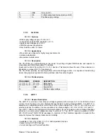
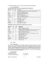
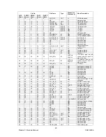
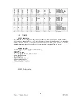
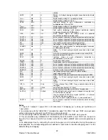
12.22.3. Pinning 


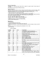
SYMBOL PIN 

TYPE 

DESCRIPTION 

XTOUT  

A2  

O  

crystal oscillator output signal; auxiliary signal 

XTALO  

A3  

O  

24.576 MHz (32.11 MHz) crystal oscillator output; not 
connected if TTL clock input of XTALI is used 

SS(xtal)


A4  

P  

ground for crystal oscillator 

TDO  

A5  

O  

test data output for boundary scan test; note 2 

XRDY  

A6  

O  

task flag or ready signal from scaler, controlled by XRQT 

XCLK  

A7  

I/O  

clock I/O expansion port 

XPD0  

A8  

I/O  

LSB of expansion port data 

XPD2  

A9  

I/O  

MSB - 5 of expansion port data 

XPD4  

A10  

I/O  

MSB - 3 of expansion port data 

XPD6  

A11 

I/O  

MSB - 1 of expansion port data 

TEST1 

A12 

I/pu 

do not connect, reserved for future extensions and for testing: 
scan input 

TEST2  

A13  

I/pu  

do not connect, reserved for future extensions and for testing: 
scan input 

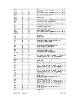
AI41  

B1  

I  

analog input 41 

TEST3  

B2  

O  

do not connect, reserved for future extensions and for testing 

DD(xtal)


B3  

P  

supply voltage for crystal oscillator 

XTALI  

B4  

I  

input terminal for 24.576 MHz (32.11 MHz) crystal oscillator 
or connection of external oscillator with TTL compatible 
square wave clock signal 

TDI  

B5  

I/pu  

test data input for boundary scan test; note 2 

TCK  

B6  

I/pu  

test clock for boundary scan test; note 2 

XDQ  

B7  

I/O  

data qualifier for expansion port 

XPD1  

B8  

I/O  

MSB - 6 of expansion port data 

XPD3  

B9  

I/O  

MSB - 4 of expansion port data 

XPD5 

B10 

I/O 

MSB - 2 of expansion port data 

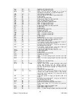
XTRI  

B11 

I  

X-port output control signal, affects all X-port pins (XPD7 to 
XPD0, XRH, XRV, XDQ and XCLK), enable and active 
polarity is under software control (bits XPE in subaddress 

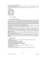
Summary of Contents for 17MB11

Page 1: ...50 PLASMA TV 17MB11 SERVICE MANUAL...

Page 2: ...eral Description 6 12 3 2 Features 6 12 3 3 Pinning 7 12 4 TEA6415C 7 12 4 1 General Description 7 12 4 2 Features 8 12 4 3 Pinning 8 12 5 SAA3010T 8 12 5 1 Description 8 12 5 2 Features 8 12 5 3 Pinn...

Page 3: ...18 1 Description 21 12 18 2 Features 21 12 18 3 Pin Connection 21 12 19 TDA1308 22 12 19 1 General Description 22 12 19 2 Features 22 12 19 3 Pinning 22 12 20 PI5V330 22 12 20 1 General Description 2...

Page 4: ...ption 35 12 29 2 Features 36 12 29 3 Pin Descriptions 36 12 30 FLASH 8MBit 37 12 30 1 Description 37 12 30 2 Features 37 12 31 LM2576 37 12 31 1 Description 37 12 31 2 Features 38 12 31 3 Pin Descript...

Page 5: ...e low IF output impedance has been designed for direct drive of a wide variety of SAW filters with sufficient suppression of triple transient Features of UV1316 1 Member of the UV1300 family small siz...

Page 6: ...any adjustments 5 VIDEO SWITCH TEA6415 In case of three or more external sources are used the video switch IC TEA6415 is used The main function of this device is to switch 8 video input sources on the...

Page 7: ...serial master slave interface modules that can be multiplexed to control up to five 2 wire serial ports The slave 2 wire interface is designed for HDCP use only and requires the use of HDCP Image Pro...

Page 8: ...0 Terminals Tinned CuFe alloy Pin configuration 1 Input 2 Input ground 3 Chip carrier ground 4 Output 5 Output 12 IC DESCRIPTIONS MC34063 24LC32 TDA9886 TEA6415C SAA3010T 24C32 SAA5264 LM317T LM393 ST...

Page 9: ...ically Erasable PROM capable of operation across a broad voltage range 2 5V to 6 0V This device has been developed for advanced low power applications such as personal communications or data acquisiti...

Page 10: ...yte or page Factory programming QTP available Up to 8 devices may be connected to the same bus for up to 256K bits total memory Electrostatic discharge protection 4000V Data retention 200 years 8 pin...

Page 11: ...tchable via I2 C bus AM demodulator without extra reference circuit Alignment free selective FM PLL demodulator with high linearity and low noise I2 C bus control for all functions I2 C bus transceive...

Page 12: ...lock Low level 0 3V Max 1 5V High level 3 0V Max Vcc 0 5V 5 Input Max 2Vpp Input Current 1mA Max 3mA 6 Input Max 2Vpp Input Current 1mA Max 3mA 7 Prog 8 Input Max 2Vpp Input Current 1mA Max 3mA 9 Vcc...

Page 13: ...cycles guaranteed 32 byte page or byte write modes available Schmitt trigger filtered inputs for noise suppression Output slope control to eliminate ground bounce 2 ms typical write cycle time byte o...

Page 14: ...Wide Screen Signalling WSS decoding Pan European Cyrillic Greek Turkish and French Arabic character sets in each chip High level command interface via I2 C bus gives easy control with a low software...

Page 15: ...Signal CVBS input a positive going 1V CVBS1 24 I peak to peak input is required connected via a 100 nF capacitor SYNC_FILTER 25 I sync pulse filter input for CVBS this pin should be connected to VSSA...

Page 16: ...only a resistive divider making the device exceptionally easy to use and eliminating the stocking of many fixed regulators 12 8 2 Features Output voltage range 1 2 To 37V Output current In excess of 1...

Page 17: ...nal mode to the Transmit Only mode except when the power supply is removed The device operates with a power supply value as low as 2 5V Both Plastic Dual in Line and Plastic Small Outline packages are...

Page 18: ...ion the TLC77xx power has to be supplied by the battery The TLC77xxQ is characterized for operation over a temperature range of 40 C to 125 C and the TLC77xxI is characterized for operation over a tem...

Page 19: ...tter free output signals 12 13 4 Pin Description PIN NUMBER SYMBOL DESCRIPTION 1 3 5 9 11 13 1A 6A Data inputs 2 4 6 8 10 12 1Y 6Y Data outputs 7 GND Ground 0V 14 Vcc Positive supply voltage 12 14 LM1...

Page 20: ...97 5 Mbytes sec Also available is the DS90C365 that converts 21 bits of LVCMOS LVTTL data into three LVDS Low Voltage Differential Signaling data streams Both transmitters can be programmed for Rising...

Page 21: ...ta output TxCLKIN I 1 TTL Ievel clock input The rising edge acts as data strobe Pin name TxCLK IN R_FB I 1 Programmable strobe select HIGH rising edge LOW falling edge TxCLK OUT O 1 Positive LVDS diff...

Page 22: ...ming to the standard recommended by the Broadcast Television Systems Committee BTSC The DBX noise reduction or alternatively MICRONAS Noise Reduction MNR is performed alignment free Other processed st...

Page 23: ...us change Loudspeaker Headphone channel with volume balance bass treble loudness AVC Automatic Volume Correction Subwoofer output with programmable low pass and complementary high pass filter 5 band g...

Page 24: ...6 66 49 AVSUP OBL Analog power supply 5V 65 AVSUP OBL Analog power supply 5V 64 NC LV Not connected 63 NC LV Not connected 27 56 45 62 48 AVSS OBL Analog ground 61 AVSS OBL Analog ground 28 55 44 60 4...

Page 25: ...d 67 18 16 13 10 DVSUP OBL Digital power supply 5V 12 DVSUP OBL Digital power supply 5V 11 DVSUP OBL Digital power supply 5V 68 17 15 10 9 ADR_CL OUT LV ADR clock 12 18 TDA8928 12 18 1 Description The...

Page 26: ...temperature range No switch ON OFF clicks Excellent power supply ripple rejection Low power consumption Short circuit resistant High performance High signal to noise ratio High slew rate Low distortio...

Page 27: ...orkstations With a sampling rate capability of up to 140 MHz it can accurately support display resolutions up to 1280x1024 SXGA at 75 Hz The clamped input circuits provide sufficient bandwidth to accu...

Page 28: ...uit It is a highly integrated circuit for desktop video and similar applications The decoder is based on the principle of line locked clock decoding and is able to decode the colour of PAL SECAM and N...

Page 29: ...colour and cross luminance artifacts PAL delay line for correcting PAL phase errors Brightness Contrast Saturation BCS adjustment separately for composite and baseband signals User programmable sharpn...

Page 30: ...complies with the IEEE Std 1149 b1 1994 BGA156 package 12 22 3 Pinning SYMBOL PIN TYPE DESCRIPTION XTOUT A2 O crystal oscillator output signal auxiliary signal XTALO A3 O 24 576 MHz 32 11 MHz crystal...

Page 31: ...ertical reference I O expansion port VSSD3 D9 P digital ground 3 peripheral cells VSSD4 D10 P digital ground 4 core VSSD5 D11 P digital ground 5 peripheral cells VDDD5 D12 P digital supply voltage 5 p...

Page 32: ...ddresses 84H and 85H IGPV K14 O multi purpose vertical reference output signal image port controlled by subaddresses 84H and 85H VDDA1A L1 P analog supply voltage for analog inputs AI1x 3 3 V AGNDA L2...

Page 33: ...esting TEST18 P2 I O do not connect reserved for future extensions and for testing EXMCLR P3 I pd external mode clear with internal pull down LLC P4 O line locked system clock output 27 MHz nominal RE...

Page 34: ...d Standby current is less than 1 A Each regulator option is available in either a SOT223 5 D TPS72501 only or DDPAK package With a low input voltage and properly heatsinked package the regulator dissi...

Page 35: ...settling time after power on 200_s 12 25 PCF8591 12 25 1 General Description The PCF8591 is a single chip single supply low power 8 bit CMOS data acquisition device with four analog inputs one analog...

Page 36: ...y digital video signal processor that incorporates Pixelworks patented deinterlacing scaling and video enhancement algorithms The PW1231 accepts industry standard video formats and resolutions and con...

Page 37: ...frame rate conversion and enhanced video processing completely on chip A separate memory is dedicated to storage of on screen display images and CPU general purpose use Advanced video processing tech...

Page 38: ...re programmed HDCP eys to simplify manufacturing and provide the highest level of security 12 28 2 Features Integrated 25 165MHz PanelLink DVI 1 0 compliant core supports VGA to UXGA resolutions Suppo...

Page 39: ...or WRITE command are used to select the starting column location for the burst access The SDRAM provides for programmable READ or WRITE burst lengths of 1 2 4 or 8 locations or the full page with a bu...

Page 40: ...selection on systems with multiple banks CS is considered part of the command code 16 17 18 WE CAS RAS Input Command Inputs WE CAS and RAS along with CS define the command being entered 39 x4 x8 DQM...

Page 41: ...ten to the device in cycles of commands to a Command Interface using standard microprocessor write timings 12 30 2 Features 2 7V to 3 6V Supply Voltage for Program Erase and Read Operations Access Tim...

Page 42: ...load conditions The oscillator frequency is guaranteed to 10 External shutdown is included featuring less than 200 A standby current The output switch includes cycle bycycle current limiting and ther...

Page 43: ...it the service menu press M button Entire service menu parameters of Plasma TV are listed below 13 1 display menu By pressing buttons select the first icon display menu appears on the screen blank col...

Page 44: ...ss e f button to set the subwoofer level Subwoofer level can be adjusted between 0 and 32 agc adjustment Adjustment for automatic gain control of tuner By pressing c d button select agc adjustment Pre...

Page 45: ...f color temp is set as user then R G B settings can be adjusted By pressing c d button select Red Green or Blue Press f button to increase the color value Press e button to decrease the color value R...

Page 46: ...ing values main tuner By pressing c d button select main tuner Press e f button to set a tuner as main tuner pip tuner By pressing c d button select pip tuner Press e f button to set a tuner as pip tu...

Page 47: ...e f button bad cut By pressing c d button select vof Bad cut can be set to on or off by pressing e f button nr threshold By pressing c d button select nr threshold Nr threshold can be set to low or h...

Page 48: ...n Brightness contrast sharpness color volume and headphone volume factory settings can be seen in this menu When factory reset is selected in the calibration menu the values in the factory settings me...

Page 49: ...R 8 Ohms 12W HP_L R PW181A PW1231 MT48LC4M16A2 SDRAM A0 A13 14 D0 D15 16 MT28F800B3W Flash Memory A0 A19 20 D0 D15 16 RGB 24 DS90C385 LVDS TX S Video_Y_IN S Video_C_IN TEA6415 Video Switch SC1_V_OUT...

Page 50: ...47 Plasma TV Service Manual 25 08 2005 15 CIRCUIT DIAGRAMS...

Page 51: ...48 Plasma TV Service Manual 25 08 2005...

Page 52: ...49 Plasma TV Service Manual 25 08 2005...

Page 53: ...50 Plasma TV Service Manual 25 08 2005...

Page 54: ...51 Plasma TV Service Manual 25 08 2005...

Page 55: ...52 Plasma TV Service Manual 25 08 2005...

Page 56: ...53 Plasma TV Service Manual 25 08 2005...

Page 57: ...54 Plasma TV Service Manual 25 08 2005...

Page 58: ...55 Plasma TV Service Manual 25 08 2005...
Page 59: ...56 Plasma TV Service Manual 25 08 2005...

Reviews: