8
Plasma TV Service Manual
05/01/2006
Chroma input (with external resistor bridge). All the switching possibilities are changed through the
BUS. Driving 75
Ω
load needs an external transistor. It is possible to have the same input connected to
several outputs. The starting configuration upon power on (power supply: 0 to 10V) is undetermined. In
this case, 6 words of 16 bits are necessary to determine one configuration. In other case, 1 word of 16
bits is necessary to determine one configuration.
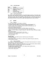
12.4.2. Features
• 20MHz Bandwidth
• Cascadable with another TEA6415C (Internal address can be changed by pin 7 voltage)
• 8 Inputs (CVBS, RGB, MAC, CHROMA,...)
• 6 Outputs
• Possibility of MAC or chroma signal for each input by switching-off the clamp with an external resistor
bridge
• Bus controlled
• 6.5dB gain between any input and output
• 55dB crosstalk at 5mHz
• Fully ESD protected
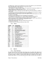
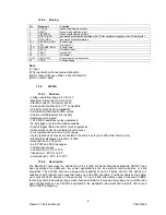
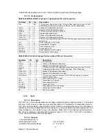
12.4.3. Pinning
1.
Input
:
Max
: 2Vpp, Input Current: 1mA, Max : 3mA
2.
Data
:
Low level
: -0.3V Max: 1.5V,
High level
: 3.0V Max
: Vcc+0.5V
3.
Input
:
Max
: 2Vpp, Input Current: 1mA,
Max
: 3mA
4.
Clock
:
Low level
: -0.3V Max: 1.5V,
High level
: 3.0V Max
: Vcc+0.5V
5.
Input
:
Max
: 2Vpp, Input Current: 1mA, Max : 3mA
6.
Input
:
Max
: 2Vpp, Input Current: 1mA, Max : 3mA
7. Prog
8.
Input
:
Max
: 2Vpp, Input Current: 1mA, Max: 3mA
9. Vcc
: 12V
10.
Input
:
Max
: 2Vpp, Input Current: 1mA, Max : 3mA
11.
Input
:
Max
: 2Vpp, Input Current: 1mA, Max : 3mA
12. Ground
13.
Output :
5.5Vpp,
Min : 4.5Vpp
14.
Output :
5.5Vpp,
Min : 4.5Vpp
15.
Output :
5.5Vpp,
Min : 4.5Vpp
16.
Output :
5.5Vpp,
Min : 4.5Vpp
17.
Output :
5.5Vpp,
Min : 4.5Vpp
18.
Output :
5.5Vpp,
Min : 4.5Vpp
19. Ground
20.
Input
:
Max : 2Vpp, Input Current
: 1mA, Max
: 3mA
12.5. SAA3010T
12.5.1. Description
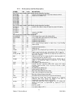
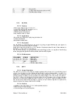
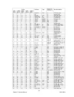
The SAA3010 is intended as a general purpose (RC-5) infrared remote control system for use where a low
voltage supply and a large debounce time are expected.
The device can generate 2048 different commands
and utilizes a keyboard with a single pole switch for each key. The commands are arranged so that 32
systems can be addressed, each system containing 64 different commands. The circuit response to legal
(one key pressed at a time) and illegal (more than one key pressed at a time) keyboard operation is specified
in the section “Keyboard operation”.
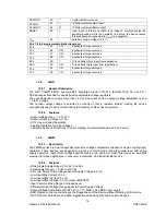
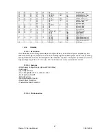
12.5.2. Features
Low voltage requirement
Biphase transmission technique
Single pin oscillator
Test mode facility
Summary of Contents for 17MB11
Page 1: ...50 PLASMA TV 17MB11 SERVICE MANUAL...
Page 50: ...47 Plasma TV Service Manual 25 08 2005 15 CIRCUIT DIAGRAMS...
Page 51: ...48 Plasma TV Service Manual 25 08 2005...
Page 52: ...49 Plasma TV Service Manual 25 08 2005...
Page 53: ...50 Plasma TV Service Manual 25 08 2005...
Page 54: ...51 Plasma TV Service Manual 25 08 2005...
Page 55: ...52 Plasma TV Service Manual 25 08 2005...
Page 56: ...53 Plasma TV Service Manual 25 08 2005...
Page 57: ...54 Plasma TV Service Manual 25 08 2005...


