background image


2021.A 


10. 

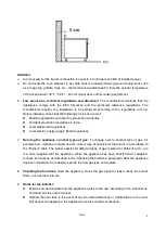
Room ventilation:   


The  room  where  the  appliance  is  installed  must  be  fitted  with  air  intakes  to  guarantee  the 

correct  operation  of  the  unit  and air  exchange.  Air necessary  for  the  burner combustion  is 

equal  to  2  cum/h  per  each  kW  of  installed  power.  The  air  intakes  must  be  of  adequate 

dimensions, be protected by grids and positioned free of any obstruction. 


Do  not  install  the  appliance  close  to  other  units  that  can  reach  high  temperature:  the 

electrical components might be damaged. 


During  installation,  make  sure  the  air  suction  and  evacuation  ways  are  free  from  any 

obstacles. 


11. 

Users should observe the following warnings: 

——

Improper installation may lead to property loss or casualty. 

——

Installation of gas appliance should be performed strictly in accordance with the instructions 

or relevant provisions. 

——

Component maintenance and replacement should be done only by authorized agent or 

professional technicians. 

——

Do not dismantle any sealing element in the gas appliance. 

——

For appliance operation, operator only. 


4.2 Gas Connection 

 
1.  The  serial  plate  is  located  inside  the  lower  front  panel.  It  indicates  the  type  of  gas  the  unit  is 

equipped to burn. All our equipment is adjusted at the factory. Check type of gas on serial plate. 

2.  The  appliance  is  design-certified  for  operation  on  natural  or  propane  gases,  it  should  be 

connected only to the type of gas for which it is equipped. 

3.  A  3/4"  NPT  line  is  provided  at  the  rear  for  the  gas  connection.  An  adequate  gas  supply  is 

imperative.  Undersized  or  low  pressure  lines  will  restrict  the  volume  of  gas  required  for   

satisfactory performance. Fluctuations of more than 25% on natural gas or 10% on propane gas 

will create problems and affect burner operating characteristics. 

4.  An adequate gas supply line to the unit should be no smaller than the inside diameter of the pipe 

from the unit to which it is connected. 

5.  Purge the supply line to clean out dust, dirt, or other foreign matter before connecting the line to 

the unit. 

6.  All pipe joints and connections must be tested thoroughly for gas leaks. Use only soapy water for 

testing on all gases. Never use an open flame to check for gas leaks. All connections must be 

checked for leaks after the unit has been put into operation. 


Summary of Contents for FGC100

Page 1: ...2021A FGC100 FGC200 Gas Convection Oven User s Manual ...

Page 2: ...c development Warning Any self modification wrong installation adjustment or maintenance can lead to property loss or casualty Please contact the manufacturer for any adjustment or maintenance and have the work done by a trained qualified person For your safety sake please keep the machine away from any liquid gas or other object which is flammable or explosive This appliance should not be operate...

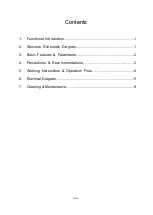
Page 3: ...nts 1 Functional Introduction 1 2 Structure Schematic Diagram 1 3 Basic Features Parameters 2 4 Precautions Recommendations 2 5 Working Instructions Operation Flow 6 6 Electrical Diagram 9 7 Cleaning Maintenance 9 ...

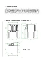
Page 4: ...lameout and a shutdown device which will stop trying to ignite the burner s after 3 attempts so as to guarantee the safe use of gas The electronic automatic thermostatic device with less temperature controlled offset could set desired cooking temperature in accordance with requirements Moreover the over temperature protection device prevents damages caused by temperature rise that is too high 2 St...

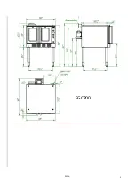
Page 5: ...2021 A 2 FGC200 ...

Page 6: ...h should be removed carefully Remove any glue residual with the proper substances such as petrol never use abrasive substances 2 Mount the unit feet the unit must be leveled small differences of height can be solved by adjusting the feet 3 The connections to the gas and or electric network must be close to the appliance and easy to reach 4 We recommend placing the unit under a suction hood so that...

Page 7: ...rd regulations Local electric energy supply Board regulations 7 Running the appliance on other types of gas To change over to another type of gas for example from methane to liquid use the correct type of nozzles for the burner in accordance to the Burners table The burner nozzles for different types of gas marked in 100ths of a mm are in a case supplied with the appliance When the appliance has b...

Page 8: ...r only 4 2 Gas Connection 1 The serial plate is located inside the lower front panel It indicates the type of gas the unit is equipped to burn All our equipment is adjusted at the factory Check type of gas on serial plate 2 The appliance is design certified for operation on natural or propane gases it should be connected only to the type of gas for which it is equipped 3 A 3 4 NPT line is provided...

Page 9: ...itioned close to the cable input It is marked by a label Warning ELECTRIC GROUNDING INSTRUCTIONS This appliance is equipped with a three prong grounding plug for your protection against shock hazard and should be plugged directly into a properly grounded three prong receptacle Do not cut or remove the grounding prong from this plug 4 4 Exhaust System 1 The appliances must be positioned in suitable...

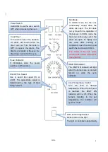
Page 10: ... is not responsible for damages due to an incorrect installation bad maintenance or incorrect use 5 Working Instructions Operation Flow 5 1 Lighting Relighting and Shutdown Instructions To light the oven just switch the power switch at the top left corner of the control panel to the ON position The oven is equipped with a direct hot surface ignition system There is no pilot to light If the burners...

Page 11: ...runs out Turn the knob to OFF to cancel the alarm The timer is a reminder to the user the timer does not control the oven HEAT ON Indicator The HEAT ON indicator will light when the burners are on and will remain on while the oven preheats Power Indicator It illuminates when the power switch is in ON position Cook Temperature Control Turn the knob to desired temperature When the set point is reach...

Page 12: ...n and close the doors 7 You can use the Cook Timer as a reminder of when to remove the load from the oven If so desired turn the Cook Timer knob until the indicator mark points to the desired cooking time up to 55 minutes The timer knob will rotate counterclockwise as the timer runs down indicating how much time remains You can turn the knob while cooking to increase or decrease the remaining time...

Page 13: ...t do not use abrasive powder detergents or corrosive substances such as hydrochloric acid muriatic or sulphuric acid The use of acids can affect the unit s operation and safety Do not use brushes steel cottons or abrasive disks made with other metals or alloys that might cause rust stains due to contamination For the same reason avoid contact with iron objects Do not use steel cottons or stainless...

Page 14: ... agreement to have the appliance checked at least once a year by the specialized personnel of our assistance service or by a specialized technician 7 Before carrying out any maintenance or repair disconnect the appliance from the gas network or cut off the mains Use only original spare parts supplied by the manufacturer 8 If the appliance is not used for long period of time please clean the equipm...

Reviews: