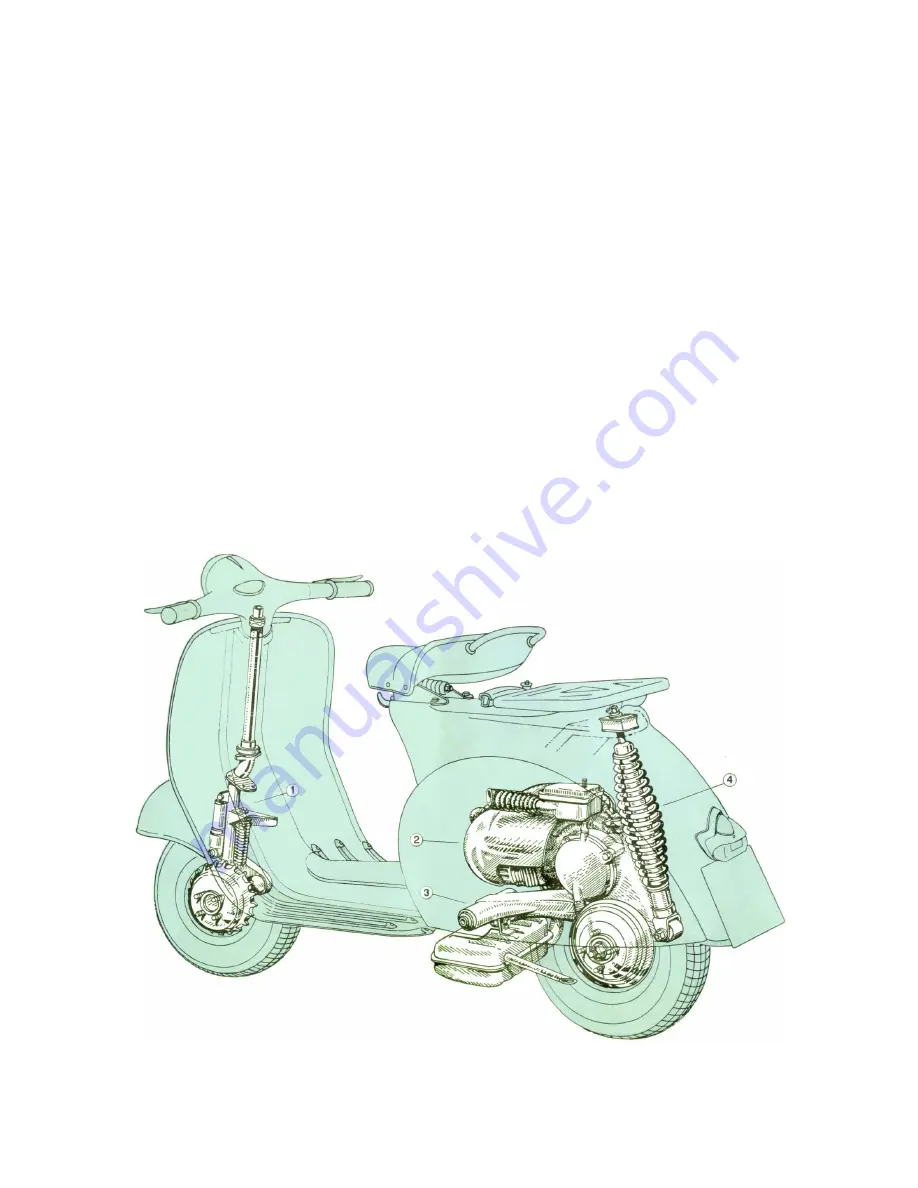
Steering column, suspension and wheels.
The steering column bears the handlebars,
clamped on its top end, and the front wheel swinging hub, pivoted at its bottom end
through a stub axle (see Fig. 9).
Front suspension
with variable rate coil spring and double action hydraulic damper.
Rear suspension:
swinging bracket for engine and rear wheel, variable rate coil spring
and coaxial, double action hydraulic tamper.
- The wheels are interchangeable with rims of pressed steel sheet (0 8").
- Tyres of dia. 3.40-8".
Saddle
of the nose-pivoted, sprung type with central spring adjustable to the driver's
weight.
Brakes.
Expanding type with cable control.
Front:
lever on R. H. side of handlebars.
Rear:
control pedal on floorboard, R. H. Drums in light alloy with cooling fins.
Central stand.
A two-legged stand, easy to operate, is arranged under the floorboard. A
strong return spring in the middle holds it in contact with the floorboard and keeps it from
vibrating while the scooter is being ridden.
Fig. 9 – Engine and suspension
1. Steering column and front suspension – 2. Engine – 3. Pivoting arm of crankcase half, clutch side –
4. Rear suspension spring and hydraulic shock absorber
Summary of Contents for 1962 150
Page 1: ......
Page 5: ...TECHNICAL DATA Fig 2 3 Stamping on frame 1 Stamping on engine 2 ...
Page 17: ...Fig 13 Pillion seat spare wheel and bracket ...
Page 27: ...Fig 20 Breaker points A Max gap 0 3 0 5 mm 0 011 0 019 ...
Page 29: ...Fig 21 Lubrication scheme A engine lubricated by fuel mixture 1 filling hole 2 draining hole ...


