


VES Andover Ltd Eagle Close Chandlers Ford Ind. Est Eastleigh Hampshire SO53 4NF
Tel: 08448 15 60 60 Fax: 02380 261204 E-mail: [email protected] Web: www.ves.co.uk
ecovent
NRG
Air Handling Units
Installation, Operation and Maintenance Manual
7
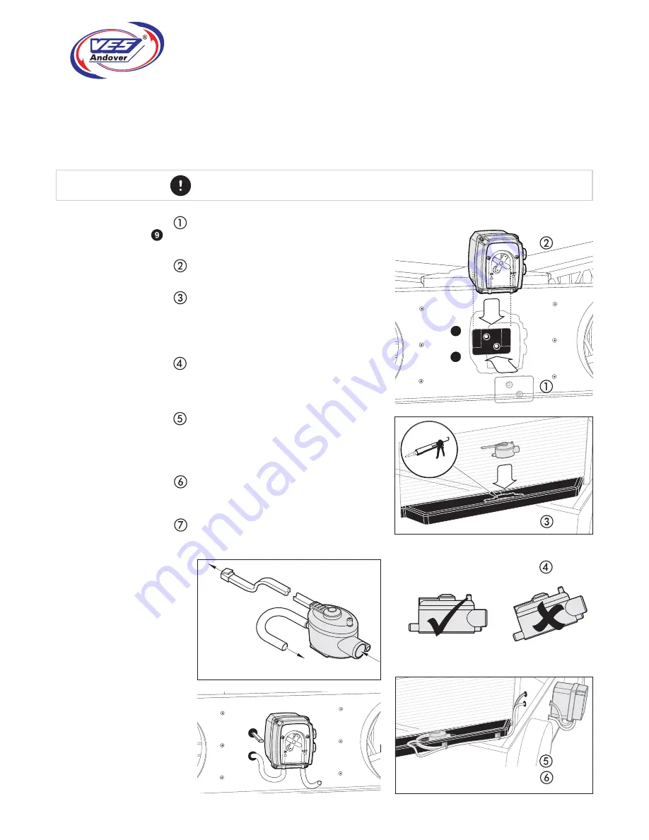
Continued
A drain pan has been provided for use in particular conditions when condensation may form within
the heat exchanger in the unit. The drain pan has been specifi cally designed for use with a
peristaltic pump assembly, also available from VES, and has been designed to allow the pump
sensor to be seated within a small sump to allow condensation collection as required.
For full fi tting/installation instructions see the documentation accompanying the pump assembly.
Installation
Size 0/1/2
Drain pump & sensor
4
Fix the pump mounting plate to the unit.
Ensure placement is the correct way up,
taking special notice on bottom access units
Slide the pump down onto the bracket as
shown.
Fit the pump sensor in the drain pan sump
as shown. Secure the sensor into place using
silicon or similar, taking care not to block the
any of the sensor connections. Give full time
for adhesive to dry before use.
It is important that the sensor/drain pan
assembly is level. Failure to do so may cause
the pump sensor to become inoperative and
so disable the pump.
Make the required connections as per the
pump O&M, ensuring that all associated
pipe work and wiring inside the unit is
carefully stowed so as not to foul on any
moving components.
Knock-outs have been provided in the unit
casework to allow for best routing.
Gland/grommet as required.
Connect the drain to an appropriate waste
system. Follow the post-installation
instructions as supplied with the pump.
Suggested routing
(components removed for clarity only)
Important
Electrical
connection
Pump sensor
Outlet
Inlet
Pump installation
Fig.


