14
Vertiv | Vertiv
Solutions
Commander
(VSC) – QuickStart
Guide | 03.951.421.0.050 | Index
A | ECR
no.
18652 I 11/18
DEUTSCH
ENGLISH
3.2 VSC mit dem Netzwerk
verbinden
1
2
3
5
6
7
4
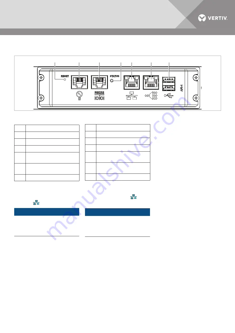
Abb. 7:
Netzwerk-Schnittstellen des Vertiv
Solutions Commander
1
Reset-Taste
2
Externer Sensor-Port
3
Port RS232
4
Status-Anzeige
5
LAN-Port (NBI,
Northbound-Interface)
6
Management-Port (SBI,
Southbound-Interface)
7
USB-Schnittstellen
1. Um dem VSC eine dynamische
IP-Adresse (DHCP) zuzuweisen, ver-
binden Sie den VSC über den LAN-
Port (5)
.
HINWEIS
Um Konflikte zwischen dem DHCP-
Server und dem VSC zu vermeiden, darf
der Management-Port (6) NICHT mit
dem Netzwerk verbunden werden.
2. Schließen Sie die Sensoren an.
3. Schalten Sie den VSC ein.
Die Status-Anzeige des VSC leuchtet
grün.
4. Schließen Sie den Netzwerk-Switch
an.
5. Schalten Sie die in das Southbound-
Netzwerk eingebundenen Geräte
nacheinander ein und beachten Sie
dabei die Status-Anzeigen.
3.2 Connect VSC to the
network
Fig. 7:
Network interfaces of the Vertiv
Solutions Commander
1
Reset button
2
External sensor port
3
Port RS232
4
Status display
5
LAN-Port (NBI,
Northbound-Interface)
6
Management-Port (SBI,
Southbound-Interface)
7
USB interfaces
1. To assign a dynamic IP address
(DHCP) to the VSC, connect the
VSC via the LAN port (5)
.
NOTE
To avoid conflicts between the DHCP
server and the VSC, the management
port (6) must NOT be connected to the
network.
2. Connect the sensors.
3. Switch on the VSC.
The VSC‘s status indicator lights
green.
4. Connect the network switch.
5. Switch on the devices connected to
the Southbound network one after the
other and pay attention to the status
displays.
INBETRIEBNAHME
COMMISSIONING


