Vertiv Liebert CW Installer/User Manual Download Page 52

           REV :   2
REV DATE :   6/18

DPN004351
Page :2 /2

F

or

m

 N

o.

: D

P

N

00

10

40

_R

E

V

4

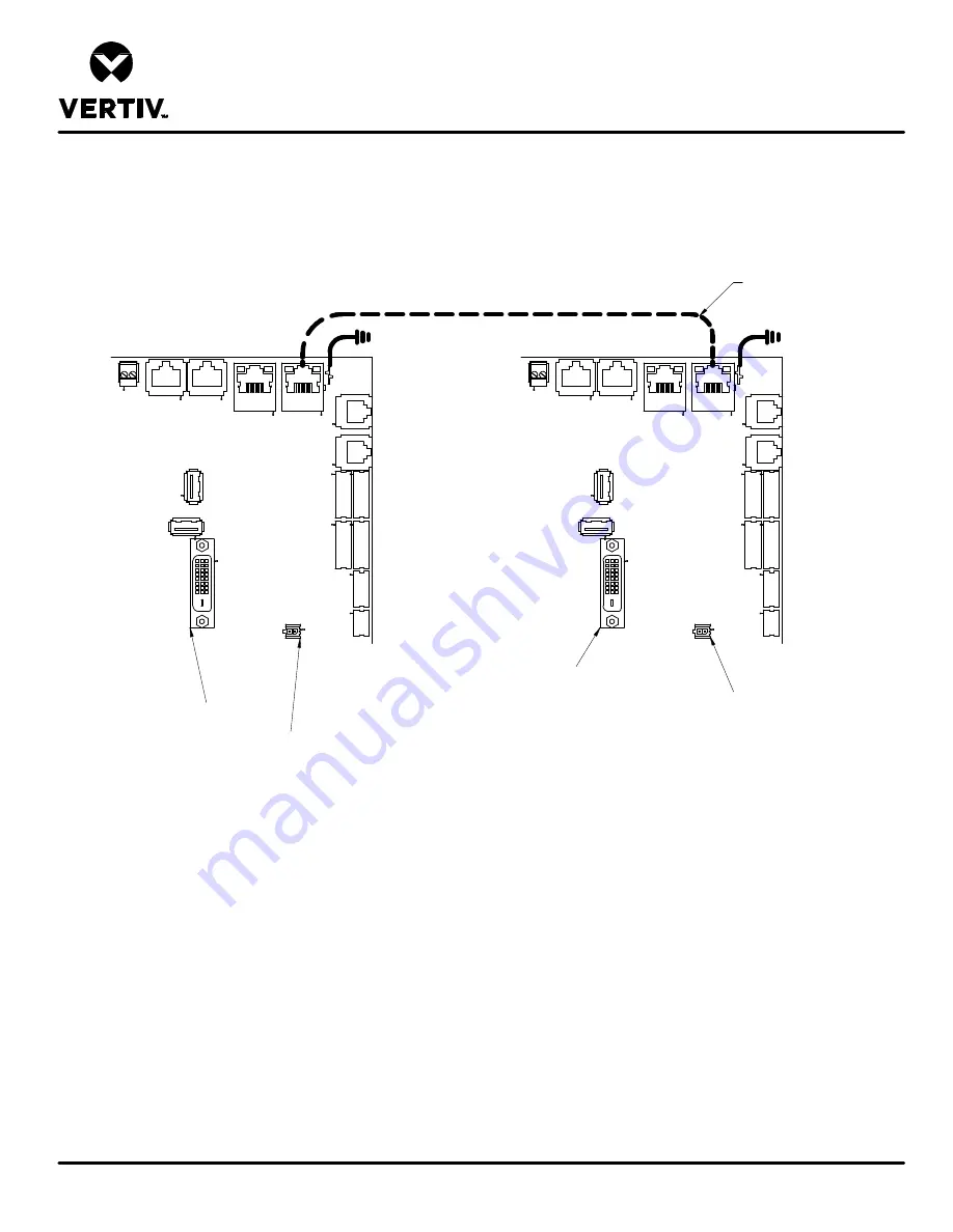
UNIT TO UNIT NETWORK CONNECTIONS

LIEBERT DS, DSE, CW, PDX & PCW

ETHERNET CABLE
(FIELD SUPPLIED)

TB3

P71

P72

P74

P64

E5

P

67

P

66

P

11

P

12

P

21

P

20

P

13

P

7

P76

P95

P100

P75

2

iCOM

MICROPROCESSOR 

AND I/O BOARD

TB3

P71

P72

P74

P64

E5

P

67

P

66

P

11

P

12

P

21

P

20

P

13

P

7

P76

P95

P100

P75

2

iCOM

MICROPROCESSOR 

AND I/O BOARD

NOTE* For dual-unit network configurations only

P95 DVI-D CABLE CONNECTION
TO 7-INCH ICOM DISPLAY

P100 POWER SUPPLY TO 
7-INCH ICOM DISPLAY

P95 DVI-D CABLE CONNECTION
TO 7-INCH ICOM DISPLAY

P100 POWER SUPPLY TO 
7-INCH ICOM DISPLAY

Summary of Contents for Liebert CW

Page 1: ...Liebert CW Thermal Management System Installer User Guide 305 kW 375 kW 415 kW Capacity 50 60 Hz...

Page 2: ...s all liability for damages resulting from use of this information or for any errors or omissions Refer to other local practices or building codes as applicable for the correct methods tools and mater...

Page 3: ...onnections 24 5 1 1 Field installed Gravity fed Drain Line Requirements 24 5 1 2 Condensate pump Drain Line Requirements 25 5 2 Chilled water Loop Piping Guidelines 25 5 2 1 Leak Checking for Unit and...

Page 4: ...9 Preventive Maintenance Checklist 39 Appendices 43 Appendix A Technical Support and Contacts 43 Appendix B Submittal Drawings 45 Vertiv Liebert CW Installer User Guide iv...

Page 5: ...er does not isolate power from the unit even in the Unit Off mode Some internal components require and receive power even during the Unit Off mode of the controller The only way to ensure that there i...

Page 6: ...tion and service of this equipment should be done only by qualified personnel who have been specially trained in the installation of air conditioning equipment and who are wearing appropriate OSHA app...

Page 7: ...sufficient time for them to cool to a touch safe temperature before working within the unit cabinet Use extreme caution and wear appropriate OSHA approved PPE when working on or near hot components CA...

Page 8: ...omponents and piping The water coolant fluid must be treated and circulating through the system continuously to prevent the buildup of sediment deposits and or growth of sulfate reducing bacteria Prop...

Page 9: ...water leakage from the unit Water leakage can result in catastrophic and expensive building and equipment damage and loss of critical data center equipment Do not locate unit directly above any equipm...

Page 10: ...Vertiv Liebert CW Installer User Guide 6 This page intentionally left blank...

Page 11: ...mber Detail Digits 11 to 25 Example 26 27 28 29 30 31 32 33 34 35 36 0 0 0 0 0 0 0 0 0 0 0 Table 1 3 CW onfiguration number Detail Digits 26 to 36 37 38 39 40 A Table 1 4 CW Model Number Digits 37 to...

Page 12: ...rol 2 iCOM high definition Digit 13 Humidification 0 None Digit 14 Air Filter 8 4 in MERV 8 9 4 in MERV 11 Digit 15 Coil 2 Hydrophilic coated evap coil Digit 16 Seismic 0 None Digit 17 High voltage Op...

Page 13: ...Digit 21 Packaging P Domestic C Export Digit 22 23 24 25 Placeholder 0 Placeholder Digit 26 Power Meter 0 None P Power Meter Digits 27 and 28 Placeholder 0 Placeholder Digit 29 Condensate Pump 0 None...

Page 14: ...in the Submittal Drawings on page 45 The following table lists the relevant documents by number and title Document Number Title DPN004861 Component Location HorizontalDischarge DPN004899 Component Loc...

Page 15: ...an alcove or at the end of a long narrow room Install the units as close as possible to the largest heat load Allow at least the minimum recommended clearances for maintenance and service See the appr...

Page 16: ...point is 59 F 15 C The recommended minimum return air temperature setpoint for the CW is 85 F 29 4 C 2 3 1 Cooling Dehumidification and Humidification Return air to the unit must be no cooler than th...

Page 17: ...arp edges splinters and exposed fasteners Can cause injury Only properly trained and qualified personnel wearing appropriate OSHA approved PPE should attempt to move lift remove packaging from or prep...

Page 18: ...table spread to the widest allowable distance that will fit under the skid When moving the packaged unit lift the unit from the end with the indicated labeling and do not lift the unit any higher than...

Page 19: ...packaging planks On units with export packaging remove the metal spring clips that secure the top and side panels of the crate Then remove the exterior stretch wrap packaging from around the unit and...

Page 20: ...could occur to the panels and or base of the unit 1 Referring to Figure 3 3 below use a 9 16 in socket driver to remove the lag screws 24 total from the 4 corner brackets to detach the unit from the...

Page 21: ...instructions included in the kit install the rigging hardware for lifting the unit from the skid Figure 3 4 below shows an example of one of the eye nuts installed Figure 3 4 Rigging fastener eye nut...

Page 22: ...t to the eye nuts installed in Step 2 4 Using the rigging equipment lift the unit from the skid and remove the skid from under the unit see Figure 3 5 below Figure 3 5 Lifting unit and removing skid V...

Page 23: ...5 Use the rigging equipment to move the unit to the final installation location see Figure 3 6 below Figure 3 6 Moving the unit with rigging 3 Equipment Inspection and Handling 19...

Page 24: ...Vertiv Liebert CW Installer User Guide 20 This page intentionally left blank...

Page 25: ...ide the unit is to install and open a remote disconnect switch Refer to unit electrical schematic Follow all local codes WARNING Risk of improper wiring piping moving lifting and handling Can cause eq...

Page 26: ...right facing electrical piping compartment DPN004923 Connection Locations DataHallwith horizontal discharge Front right facing electrical piping compartment DPN004903 Connection Locations Bottom disch...

Page 27: ...parallel to the air flow The pipe connection locations piping general arrangement and schematics are described in the submittal documents included in the Submittal Drawings on page 45 The following ta...

Page 28: ...wing water can cause equipment and building damage Install an external 5 1 2 in trap in the drain line if desired The factory unit does not contain a trap Sagging condensate drain lines may inadverten...

Page 29: ...ding damage When the cooling unit or piping may be exposed to freezing temperatures charge the system with the proper percentage of glycol and water for the coldest design ambient temperature Automoti...

Page 30: ...m coolant fluid system pressure in case of a catastrophic fluid leak NOTICE Risk of no flow condition Can cause equipment damage Do not leave the water coolant fluid supply circuit in a no flow condit...

Page 31: ...ng leak checking of field installed piping When the units are included in a leak test use of fluid for pressure testing is recommended When pressurized gas is used for leak testing the unit the maximu...

Page 32: ...Vertiv Liebert CW Installer User Guide 28 This page intentionally left blank...

Page 33: ...und 6 Control transformer setting matches incoming power 7 Electrical service conforms to national and local codes 8 Check blowers for proper rotation 6 3 Piping Installation Checks 1 Piping completed...

Page 34: ...Vertiv Liebert CW Installer User Guide 30 This page intentionally left blank...

Page 35: ...only by qualified personnel who have been specially trained in the installation of air conditioning equipment and who are wearing appropriate OSHA approved PPE CAUTION Risk of smoke generation Can cau...

Page 36: ...Vertiv Liebert CW Installer User Guide 32 This page intentionally left blank...

Page 37: ...supply disconnect switches and verify with a voltmeter that power is off before working within any electric connection enclosures Service and maintenance work must be performed only by properly traine...

Page 38: ...OM user manual SL 31075 available at www Vertiv com for instructions on using the controller to predict some service maintenance intervals We recommend the use of trained and authorized service person...

Page 39: ...ve stopped rotating before working in the unit cabinet or on the fan assembly If control voltage is applied the fan motor can restart without warning after a power failure Do not operate the unit with...

Page 40: ...approval of Vertiv WARNING Risk of electric shock Can cause serious injury or death Open all local and remote electric power supply disconnect switches and verify with a voltmeter that power is off b...

Page 41: ...of improper power supply connection Can cause equipment damage and loss of warranty coverage Prior to connecting any equipment to a main or alternate power source for example back up generator system...

Page 42: ...f with a voltmeter before working within the condensate pump electrical connection enclosure The Liebert iCOM does not isolate power from the unit even in the Unit Off mode Some internal components re...

Page 43: ...ns Review the unit user manual for further information on unit operation We recommend the use of trained and authorized service personnel extended service contracts and factory certified replacement p...

Page 44: ...s in sump 2 Check operation of float s free movement 3 Check Clean discharge check valve Electrical Panel 1 Check fuses 2 Check contactors for pitting Replace if pitted 3 Check Re torque wire connecti...

Page 45: ...es for your records Compare readings information to previous maintenance worksheet To locate your local Vertiv representative for Vertiv engineered parts check https www Vertiv com en us support or Ca...

Page 46: ...Vertiv Liebert CW Installer User Guide 42 This page intentionally left blank...

Page 47: ...ert Thermal Management Products 1 800 543 2778 Liebert Channel Products 1 800 222 5877 Liebert AC and DC Power Products 1 800 543 2378 A 2 Locations United States Vertiv Headquarters 1050 Dearborn Dri...

Page 48: ...Vertiv Liebert CW Installer User Guide 44 This page intentionally left blank...

Page 49: ...Schematic DPN004865 Airflow Schematic Downflow HorizontalDischarge DPN004904 Airflow Schematic Downflow Bottom Discharge Piping Schematics DPN004952 Piping Schematic Downflow CW305 375 415 Piping Con...

Page 50: ...rizontal discharge Front right facing electrical piping compartment DPN004903 Connection Locations Bottom discharge Front left facing electrical piping compartment DPN004924 Connection Locations Galle...

Page 51: ...TB3 P71 P72 P74 P64 E5 P67 P66 P11 P12 P21 P20 P13 P7 P76 P95 P100 P75 2 RS485 ETHERNET SITE AND BMS COMMUNICATION CONNECTIONS iCOM MICROPROCESSOR AND I O BOARD ETHERNET CABLE FIELD SUPPLIED TB3 P 2 D...

Page 52: ...P13 P7 P76 P95 P100 P75 2 iCOM MICROPROCESSOR AND I O BOARD TB3 P71 P72 P74 P64 E5 P67 P66 P11 P12 P21 P20 P13 P7 P76 P95 P100 P75 2 iCOM MICROPROCESSOR AND I O BOARD NOTE For dual unit network confi...

Page 53: ...porator Coil 4 Air Filters 5 Condensate Pump optional 6 Electric Panel 7 THD Mitigation Device optional 8 VFD Assemblies Typical 3 9 575V Transformer if applicable 1 4 5 6 7 3 2 8 Notes 1 Electrical C...

Page 54: ...779mm Louvers 88 1 8 2238mm 46 1168mm 1 3 4 44mm Duct Flange 120 1 8 3050mm Fan Plenum is shipped separately and field installed Data Hall Unit configuration Front of unit Front of unit Rear of Unit G...

Page 55: ...62 4 1 8 O D Cu 22 5 8 575 POINT Description Electrical Conn High Volt Top View 6 1 4 160 20 5 8 524 Electrical Conn Low Volt Notes 1 Drawing not to scale All dimensions from left corner on service si...

Page 56: ...Earth grounding required for Liebert units 5 Unit factory installed disconnect switch and Main Fuses Access to the high voltage electric panel compartment can be obtained only with the switch in the o...

Page 57: ...d Use Class 1 field supplied wiring 13 Analog inputs Terminals 41 42 43 and 44 are user configurable for 0 10V 0 5V or 4 20MA OPTIONAL LOW VOLTAGE TERMINAL PACKAGE CONNECTIONS 14 Remote unit shutdown...

Page 58: ...3 4 5 1 2 ANALOG INPUTS SMOKE DETECTION RAD2 CPSS RAD4 RAD1 ALARM INPUTS COMMON ALARMS REMOTE SHUT DOWN REV STARTER RA RB EXTRA REMOTE SHUT DOWN EXTRA COMMON ALARM CONDENSATE PUMP LIQUITECT SHUT DOWN...

Page 59: ...Data Hall Side 114 2896mm 70 1779mm 7 1 2 189mm 10 1 2 267mm 3 76mm 1 3 4 44mm Duct Flange Notes 1 Electrical Compartment shown on left side of unit Unit may be ordered with Electrical Compartment on...

Page 60: ...stand shown in configuration for Electrical Box on the left side of the unit When unit is ordered with the Electrical Box on the right side of the unit cantilevered portion of floorstand will appear o...

Page 61: ...Data Hall Side 1 Notes 1 Gap is measured between frame members of adjacent units 2 Gasketing required only on shortest section being placed adjacent to another unit 3 View shows both Electronic Compon...

Page 62: ...s measured between frame members of adjacent units Gasketing shown is for pictorial purposes only to show edges of unit that require gap sealing Gasketing and method to be provided and applied by othe...

Page 63: ...s zone 66 1676mm Full Unit and Electrical Panel Access Full Unit and Electrical Panel Access Data Hall Notes 1 Electrical Compartment is shown on the right side of the unit Unit may be ordered with El...

Page 64: ...right side of the unit Unit may be ordered with Electrical Compartment on either side or with Electrical Compartment facing into Data Hall Wall Piping and Cables can be routed in this zone 66 1676mm...

Page 65: ...INSTALLATION AND SERVICE CLEARANCE Notes 1 Electrical Compartment is shown on the left side of the unit Unit may be ordered with Electrical Compartment on either side or with Electrical Compartment fa...

Page 66: ...6 Electric Panel 7 THD Mitigation Device optional 8 VFD Assemblies Typical 3 9 575V Transformer if applicable Notes 1 Electrical Compartment item 6 shown on left side of unit Unit may be ordered with...

Page 67: ...Data Hall Unit configuration Front of unit Front of unit Front of Unit 144 3659mm 24 1 4 616mm 25 1 8 638mm Typ 79 1 8 2009mm 88 1 8 2239mm 46 1168mm 120 1 8 3050mm 1 3 4 44mm Duct Flange Rear of Uni...

Page 68: ...ction 9 229 Electrical Conn Low Volt 1 1 2 Bottom View POINT Description Electrical Conn High Volt Top View Connection Size Opening 2 1 2 28 3 4 731 6 1 4 159 4 1 8 O D Cu N A N A Notes 1 Drawing not...

Page 69: ...2 O D Cu S Supply Pipe Connection 15 381 R Return Pipe Connection 9 229 20 5 8 524 22 5 8 575 Electrical Conn Low Volt 1 1 2 Bottom View N A N A 28 3 4 731 4 1 8 O D Cu POINT Description Electrical Co...

Page 70: ...LIEBERT CW Return Air from Data Center Supply Air to Data Center Notes 1 Electrical Compartment shown on left side of unit Unit may be ordered with Electrical Compartment on right or left side of uni...

Page 71: ...79 Electrical Conn Low Volt Connection Size Opening 2 1 2 N A N A 1 1 2 Bottom View 30 762 4 1 8 O D Cu 1 1 8 29 Notes 1 Drawing not to scale All dimensions from right corner on service side and have...

Page 72: ...Cu 1 1 4 32 POINT Description Electrical Conn High Volt Top View 6 1 4 160 3 1 4 83 Electrical Conn Low Volt Notes 1 Drawing not to scale All dimensions from right corner on service side and have a t...

Page 73: ...O D Cu 20 3 4 527 POINT Description Electrical Conn High Volt Top View 6 1 4 160 22 3 4 578 Electrical Conn Low Volt Notes 1 Drawing not to scale All dimensions from right corner on service side and...

Page 74: ...W305 375 415 Chilled Water Return Chilled Water Supply Off Valves Bibs Valve Actuator Air Flow FACTORY PIPING FIELD PIPING Bleed Valve Shut Hose Notes 1 Components are not supplied by Liebert but are...

Page 75: ...Vertiv Liebert CW Installer User Guide...

Page 76: ...nd logos referred to are trade names trademarks or registered trademarks of their respective owners While every precaution has been taken to ensure accuracyand completeness herein Vertiv Co assumes no...

Reviews: