background image

Vertiv™ XTE 802G Generator Room Walk-In-Cabinet Description and Installation Manual 


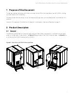
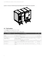
Figure 2-2:  

Illustration of XTE 802G Generator Room Mounted Next to an XTE 802 Walk-In-Cabinet (WIC) 


2.2


Part Numbers 

Refer t

Table 2-1

 for applicable product part numbers. 

Table 2-1:  

XTE 802G Generator Room Part Numbers and Descriptions 

Part Number 

Description 

NEQ 

XTE 802G Generator Room 

F2019014 

ATT 6X6 Generator Room 

BLD.44436 

Foundation Options 

D1000-0000-0101 

(stand-alone application) 

WIC Helical Foundation Kit – (4) WIC Corner Plates, (1) Two Step Stair, and (4) 6” x 7’ Helical 

Piers with Leveling Hardware. 
(two required, one for the XTE 802 and one for the XTE 802G) 

NEQ.19785 

Combo Platforms 

D1000-0010-0171 

Combo Helical Platform - (1) Platform, (2) Stairs, (4) 8" x 7' Helical Piers with Leveling 
Hardware 

NEQ.44467 

D1000-0010-0179 

Combo Concrete / On the Ground Platform - (1) Platform, (2) Stairs, (3) Skis with Leveling 

Hardware 

NEQ.44466 


Front

Summary of Contents for F2019014

Page 1: ...XTE 802G Generator Room Walk In Cabinet Description and Installation Manual Specification Number F2019014...

Page 2: ...sed in performing procedures not specifically described in this document The products covered by this instruction manual are manufactured and or sold by Vertiv This document is the property of Vertiv...

Page 3: ...ns 22 5 2 Installation Overview 22 5 3 Tools and Test Equipment Required for Installation 23 6 XTE 802G Placement 24 6 1 Overview 24 6 2 Site Selection 24 6 3 Foundation Kit Installation 25 6 3 1 Heli...

Page 4: ...Power 52 10 1 Important Safety Instructions 52 10 2 Safety Precautions 52 10 3 General 52 10 4 48 VDC Interior Lights Wiring Block 52 10 5 Optional 24 VDC Smoke Detector Wiring Junction Box 54 11 OSP...

Page 5: ...f not avoided ANSI OSHA This admonition is not used for situations that pose a risk only to equipment data or service even if such use appears to be permitted in some of the applicable standards OSHA...

Page 6: ...certified and well maintained insulated tools Use double insulated tools appropriately rated for the work to be performed Buried Utilities CAUTION When installing the enclosure ensure the site is fre...

Page 7: ...and sized in a manner that is consistent with the NEC and local codes Always use an approved voltage detector when approaching an enclosure to verify no leaks or shorts are presents on the external bo...

Page 8: ...ES If joint buried cables are used check the cable sheath for voltage in accordance with local standards If voltage is detected do not proceed with the installation Contact the supervisor and do not p...

Page 9: ...for example do not exceed the capacity of reach Crane Operation Only properly trained operators shall operate the crane Do not operate the crane until all stabilizers are extended The stabilizers mus...

Page 10: ...Vertiv XTE 802G Generator Room Walk In Cabinet Description and Installation Manual x This page intentionally left blank...

Page 11: ...iated equipment are not covered in this document Documents that supplement the information in this document are referenced in Sequence of Procedures on page 20 2 Product Description 2 1 General The XT...

Page 12: ...802G Generator Room F2019014 ATT 6X6 Generator Room BLD 44436 Foundation Options D1000 0000 0101 stand alone application WIC Helical Foundation Kit 4 WIC Corner Plates 1 Two Step Stair and 4 6 x 7 Hel...

Page 13: ...stribution equipment applications These components are intended for the installation of industrial electrical equipment and or power distribution equipment where the complete assembly is approved for...

Page 14: ...ure 2 9 for conduit knockout locations and dimensions Specifications External Dimensions 80 x 80 x 113 Internal Height 96 5 Internal Width 71 4 Internal Length 71 4 Weight Empty 2400 lbs As Installed...

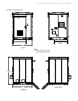
Page 15: ...Generator Room Walk In Cabinet Description and Installation Manual 5 Figure 2 3 Overall Dimensions Notes 1 All dimensions are in inches unless otherwise specified 80 00 Left Side Right Side 113 06 80...

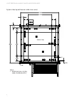
Page 16: ...t Description and Installation Manual 6 Figure 2 4 Mounting Hole Dimensions without corner plates Bottom View Front Notes 1 All dimensions are in inches unless otherwise specified 2 00 0 81 80 26 49 9...

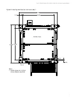
Page 17: ...lk In Cabinet Description and Installation Manual 7 Figure 2 5 Mounting Hole Dimensions with corner plates Bottom View Front Notes 1 All dimensions are in inches unless otherwise specified 68 85 82 99...

Page 18: ...Figure 2 6 Working Space Clearances Figure 2 7 Base Dimensions Top View Notes 1 All dimensions are in inches unless otherwise specified 36 48 80 00 80 00 Working Space Working Space Notes 1 All dimen...

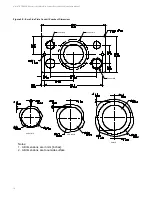
Page 19: ...s and Dimensions 20X Detail B Bottom View Typ Conduit Knockout see Detail B Front 2x 5 35 3x 5 30 14 73 14 92 2x 3 70 1 85 1 94 43 36 2 70 6 40 3x 3 70 6x 3 70 1 85 6 40 3x 3 70 2x 9 92 2x 12 34 2x 0...

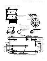
Page 20: ...Description and Installation Manual 10 Figure 2 9 Base Side Plate Conduit Knockout Dimensions Notes 1 All dimensions are in mm inches 2 All dimensions are to outside surface See Detail A See Detail C...

Page 21: ...ull support foundation Roof Live and Impact Load 300 PSF maximum Wind Speed 180 mph Protection Powder coat finish Meets GR487 Telcordia mechanical and environmental standards for telecom cabinets Prot...

Page 22: ...802G Generator Room is equipped with one lifting lug at the top of each corner that allow it to be lifted and lowered into position The base is also equipped with fork lift pockets that allow the use...

Page 23: ...mbo Helical Platform P N D1000 0010 0171 If ordered through CEEOT this platform will ship to the site completely configured with XTE 802 and XTE 802G including all conduit and cabling Consists of four...

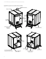
Page 24: ...s Identified Insulated Roof WIC Interconnect Panels and Hardware Exterior Ground Bar Front Front Air Intake Lifting Hinges 4 Access Panels Wide Door E Stop Switch 2 inch Insulated Wall Panels with 2 i...

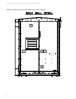
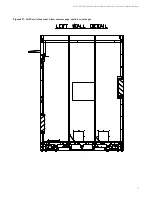
Page 25: ...Vertiv XTE 802G Generator Room Walk In Cabinet Description and Installation Manual 15 Figure 2 11 Wall Detail Views cont d on next page...

Page 26: ...Vertiv XTE 802G Generator Room Walk In Cabinet Description and Installation Manual 16 Figure 2 11 Wall Detail Views cont d from previous page cont d on next page...

Page 27: ...Vertiv XTE 802G Generator Room Walk In Cabinet Description and Installation Manual 17 Figure 2 11 Wall Detail Views cont d from previous page cont d on next page...

Page 28: ...Vertiv XTE 802G Generator Room Walk In Cabinet Description and Installation Manual 18 Figure 2 11 Wall Detail Views cont d from previous page...

Page 29: ...cription and Installation Manual 19 Figure 2 12 Top View of Floor and Floor Cable Entry Ports Figure 2 13 Door Intrusion Switch Location Roxtec Conduit Plate Front Door Empty Generator Battery Front D...

Page 30: ...2G including associated foundation options Front Door 21 Describes the front door and operation of the front door intrusion alarm switch Installation Considerations 22 Provides installation overview X...

Page 31: ...open position and an adjustable hydraulic closure 4 4 Door Intrusion Alarm Switch Operation The front door is equipped with a door intrusion alarm switch The intrusion alarm switch can be connected to...

Page 32: ...n Overview The following is the recommended sequence for the installation and start up procedures The sequence may change according to job and site conditions Ensure all site drawings and approvals ar...

Page 33: ...mmended Torque wrench Ratchet drive extensions sockets Carpenter s level Lineman s scissors Lineman s strippers Lineman s cutters Appropriate crimping tool with dies Electrician s insulated screwdrive...

Page 34: ...afe working conditions The XTE 802G should be easily accessible with adequate parking to ensure safety for people and vehicles Place the XTE 802G where it will not create a visual or physical obstruct...

Page 35: ...tachment 4 Lift helical upright allowing it to swing free of the ground 5 Maneuver the helical directly over the installation point 6 Lower the helical until the point of the helical is forced into th...

Page 36: ...68 85 inch centers between all four helicals See Figure 6 2 Figure 6 2 Helical Plate Orientations and Center to Center Adjustments 11 Install leveling hardware in the center on each helical Each helic...

Page 37: ...the XTE 802G base to the corner plates prior to releasing all of the weight of the XTE 802G on the corner plates See XTE 802G Lifting and Placement Procedures starting on page 39 15 Once all hardware...

Page 38: ...stalled at the site Simply install the helicals in the ground then lift and set the platform onto the helicals See Figure 6 6 Combo Helical Platform Installation Procedure 1 Assemble the universal dri...

Page 39: ...cedures should be used Alternative Installation Procedure 1 8 Inch Auger 1 Using an 8 inch auger drill to a depth of 5 to 7 feet while minimizing enlargement of the bore Drill the pier into the hole u...

Page 40: ...Vertiv XTE 802G Generator Room Walk In Cabinet Description and Installation Manual 30 Figure 6 6 XTE 802 and XTE 802G Combo Helical Platform...

Page 41: ...normally dry and have good drainage 2 Ground gravel should be level or very close Concrete Pier Installation Considerations 1 Height of concrete piers must be constructed to grade level If grade is no...

Page 42: ...d set it on grade or concrete in desired location 2 Level the platform by adjusting the leveling hardware between the frame and the nine leveling points Start by leveling the four corners first then a...

Page 43: ...Vertiv XTE 802G Generator Room Walk In Cabinet Description and Installation Manual 33 Figure 6 7 Combo Concrete Platform...

Page 44: ...Vertiv XTE 802G Generator Room Walk In Cabinet Description and Installation Manual 34 Figure 6 8 Combo Gravity Platform...

Page 45: ...urer and local practices for example do not exceed the capacity of reach Crane Operation Only properly trained operators shall operate the crane Do not operate the crane until all stabilizers are exte...

Page 46: ...802G may be exposed to conditions from 40 C 40 F to 46 C 115 F 6 6 Unpacking and Preparing the XTE 802G at the Installation Site Safety Precautions DANGER Do not install any additional equipment until...

Page 47: ...evises to attach the wire rope slings to the XTE 802G lifting eyebolts Connecting links should each have the capacity to support the entire shipped weight of the equipped XTE 802G to prevent potential...

Page 48: ...Vertiv XTE 802G Generator Room Walk In Cabinet Description and Installation Manual 38 Figure 6 9 Removing Base Cable Entry Covers Removable Base Cable Entry Covers...

Page 49: ...r longer use a spreader bar to be sure the cables pull on the lifting eyebolts in a vertical direction NOTE It is important that the length of each sling allow for an angle 45 degree or more NOTE Fail...

Page 50: ...Lifting the XTE 802G Typical sling arrangement Shackle Direction of pull The angle between the sling cables and the top of the cabinet shall not be less than 45 Never use the sling without clevises or...

Page 51: ...o be sure the XTE 802G is properly placed 3 Loosen the slings or remove forklift so that the full weight of the XTE 802G rests on the foundation kit 4 Secure the XTE 802G by bolting it to the mounting...

Page 52: ...tion and Installation Manual 42 Figure 6 11 Bolting XTE 802G to Pier Threaded Rod into Pier Sandwich WIC Mounting Plate Between Top Sets of Washers and Nuts Sandwich Pier Top Plate Between Bottom Sets...

Page 53: ...iption and Installation Manual 43 7 Installing Interconnect Frame A sheet metal frame is furnished to fill in the gap between the installed XTE 802 and XTE 802G Refer to Figure 7 1 for assembly detail...

Page 54: ...Vertiv XTE 802G Generator Room Walk In Cabinet Description and Installation Manual 44 Figure 7 1 Interconnect Frame cont d from previous page...

Page 55: ...ockout stampings to facilitate conduit connections 2 Route the OSP cables into the XTE 802G by removing a Roxtec port frame from the finished floor inside the XTE 802G Use a fiberglass fish tape from...

Page 56: ...al power being connected to the XTE 802G see Figure 9 2 All XTE 802G grounding must be installed prior to turn up of XTE 802G The internal XTE 802G frame and all attached equipment are factory grounde...

Page 57: ...et Description and Installation Manual 47 Figure 9 1 XTE 802G Master Ground Bar MGB Location 1 48 12X 910 11X 920 4 00 24 00 24X 438 2X 438 24X 438 x 688 OBROUND 2X 56 1 56 2X 2 00 2 44 Master Ground...

Page 58: ...Vertiv XTE 802G Generator Room Walk In Cabinet Description and Installation Manual 48 Figure 9 2 XTE 802G Ground Bar Interior Location Ground Bar Front...

Page 59: ...ovided 2 AWG solid pre lugged cable from the master ground bar to the ground connection on each WIC corner plate To WIC corner plate on opposite side To WIC corner plate on opposite side Helical Ancho...

Page 60: ...6 AWG 12 2 1 1 2 4 AWG 12 3 na 2 AWG 12 3 2 1 0 AWG 12 4 na 4 0 AWG 12 4 na 750 kcmil 12 7 na Contractor Installed Contractor Installed To the tower ground Use one provided 2 stranded cable from the...

Page 61: ...1 0 AWG 12 4 na 4 0 AWG 12 4 na 750 kcmil 12 7 na XTE 802 and XTE 802G Combo Site Grounding Concrete On the Ground Platform Foundation To the ground ring Contractor Installed Contractor Installed To...

Page 62: ...tall equipment showing any physical damage DANGER RISK OF ELECTRICAL SHOCK DC A maintenance Battery Switch Breaker does NOT isolate both legs of a battery circuit nor do the batteries have a protectiv...

Page 63: ...Vertiv XTE 802G Generator Room Walk In Cabinet Description and Installation Manual 53 Figure 10 1 Interior Lights Wiring Block...

Page 64: ...Cabinet Description and Installation Manual 54 10 5 Optional 24 VDC Smoke Detector Wiring Junction Box Connect 24 VDC to the optional smoke detector wiring junction box as shown in Figure 10 2 Figure...

Page 65: ...TRICAL SHOCK OSP CABLES If buried cables are used check the cable sheath for voltage in accordance with local standards If voltage is detected do not proceed with the installation Contact the supervis...

Page 66: ...th a door intrusion alarm switch This switch can be wired to the alarm block located on the XTE 802 See Figure 12 1 Refer also to the XTE 802 documentation Figure 12 1 Door Intrusion Alarm Switch Wiri...

Page 67: ...Vertiv XTE 802G Generator Room Walk In Cabinet Description and Installation Manual 57 This page intentionally left blank...

Page 68: ...v com Pricing and purchase orders for spare parts including but not limited to breakers cables fuses rectifier fans misc breaker and fuse panels enclosure fans doors and switches etc Phone 1 800 800 1...

Page 69: ...r Room Walk In Cabinet Description and Installation Manual Connect with Vertiv on Social Media https www facebook com vertivI https www instagram com vertiv https www linkedin com company vertiv https...

Page 70: ...are trade names trademarks or registered trademarks of their respective owners While every precaution has been taken to ensure accuracy and completeness here Vertiv Group Corp assumes no responsibili...

Reviews: