


Vertiv™ NetSure™ 512
NGBB
-48 VDC Power System User Manual
Proprietary and Confidential © 2022 Vertiv Group Corp.
42
Replacing a Battery or Load Disconnect Contactor
DANGER!
All sources of AC and DC power must be completely disconnected from this power system before performing this
procedure. Use a voltmeter to verify no DC voltage is present on the system busbars before proceeding.
NOTE!
In the following procedure, before making busbar-to-busbar connections, apply a thin coating of electrical anti-
oxidizing compound to the mating surfaces of the busbars.
Procedure
NOTE!
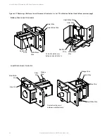
Refer to Figure 4.11 or Figure 4.12 as this procedure is performed.
Removing the Contactor
1.
Verify all AC and DC power sources are disconnected from the power system.
2.
Remove access panel(s) as required to access the following connections.
3.
Disconnect the wiring to the contactor by unplugging the quick disconnects.
4.
Note the orientation of the contactor to ensure the replacement is installed the same way. Unbolt the contactor (4-places)
and remove. Save all hardware.
Installing the Replacement Contactor
1.
Position the replacement contactor oriented the same way as the old.
2.
Secure the contactor with the hardware removed above. Refer to Figure 4.11 or Figure 4.12 for hardware build-up and
recommended torque.
3.
Replace the wiring to the contactor by plugging-in the quick disconnects. Refer to Figure 4.11 or Figure 4.12.
4.
Replace the access panel(s) removed above.
Restarting the Power System
1.
Reconnect the AC and DC power sources to the power system.
2.
Start the power system. Refer to the separate
Installation Instructions
(IM582137000) for a startup procedure.
3.
Verify no alarms are active.


